

Motor sizing starts with the driven load. A catalog can tell you what a motor is capable of, but it cannot tell you what the machine requires. The most reliable workflow is to calculate torque and speed at the motor shaft, choose a displacement range, then verify pressure, flow, speed, power, controls, case pressure, and mounting.
Practical answer: motor displacement is selected from required torque and usable pressure difference; flow is selected from required speed. Starting torque, hot-oil efficiency, return pressure, gearbox ratio and overspeed limits decide whether the first calculation will work on the machine.
Do I need starting torque or running torque?
Usually both. Running torque covers friction and process load after the machine is moving. Starting torque may be higher because of static friction, compacted material, a loaded winch drum, drivetrain preload, or cold lubricant. A motor that performs well at steady speed can still fail to start the machine.
Use measured breakaway torque when possible. When only running torque is known, apply a documented service factor based on the mechanism rather than an arbitrary blanket percentage. Also check whether a brake, valve or drivetrain preload must be released before movement begins. Apparent low starting torque may be caused by insufficient brake-release pressure or excessive mechanical resistance rather than inadequate motor displacement.
Why should I size at three duty points?
The continuous point is only one part of the job. Breakaway can demand more torque, while maximum speed can demand more flow and create higher case and flushing losses. Build a small duty table with torque, speed, time share, oil temperature and permitted pressure for each point.
Field lesson: a motor chosen only from maximum torque is often larger than necessary and may run inefficiently at normal load. A motor chosen only from normal speed may not start the machine. The gearbox and variable-displacement range should be considered before increasing pressure. For each duty point, record torque, speed, duration, oil temperature and whether the load is driving or overrunning the motor. This prevents a brief peak condition from being treated as a continuous requirement.
How do I calculate displacement from required torque?
For an initial SI estimate: Motor displacement (cm³/rev) = torque (N·m) × 62.83 ÷ [pressure difference (bar) × mechanical efficiency]
Worked example
A drive requires 900 N·m continuous motor torque. Available continuous pressure difference is 250 bar. Assume 90% mechanical efficiency.
900 × 62.83 ÷ (250 × 0.90) = 251.3 cm³/rev
A 250 cm³/rev motor is close to the calculated point. Recalculate its expected torque: Once the motor point is established, the pump flow and displacement must be matched to it.
250 × 250 × 0.90 ÷ 62.83 = 895 N·m
That is slightly below 900 N·m, so the engineer has several options:
- Increase displacement modestly.
- Increase permitted continuous pressure if the system and motor allow it.
- Increase gearbox reduction.
- Reduce load torque.
- Select a motor with better measured mechanical efficiency at the duty point.
Do not simply raise the relief setting. Hoses, valves, pump power, cooler duty, and structural loads also change.
How much flow will the motor need?
Flow (L/min) = speed (rpm) × displacement (cm³/rev) ÷ [1,000 × volumetric efficiency]
If the target is 450 rpm, displacement is 250 cm³/rev, and estimated volumetric efficiency is 92%:
450 × 250 ÷ (1,000 × 0.92) = 122.3 L/min
The pump must supply that flow at working pressure, not only at no load. Confirm valve pressure drop and line velocity because a nominal 125 L/min valve may not provide 125 L/min with an acceptable pressure loss in every spool position. The calculated flow is the flow required at the motor inlet. Also allow for any separate flushing, charge or control-flow demand, and confirm that the pump can deliver the required flow at working pressure.
What output power will reach the shaft?
Mechanical output power can be cross-checked by:
Output power (kW) = torque (N·m) × speed (rpm) ÷ 9,550
900 × 450 ÷ 9,550 = 42.4 kW
Hydraulic input at 250 bar and 122.3 L/min is: 250 × 122.3 ÷ 600 = 51.0 kW
The implied combined motor efficiency at that assumed point is about: 42.4 ÷ 51.0 = 83.1%
This does not mean the selected motor has a fixed 83.1% efficiency. It is a consistency check based on assumed volumetric and mechanical performance. Use tested data at the actual pressure, speed, displacement, and viscosity for final validation. The difference between hydraulic input power and shaft output power becomes heat and other losses. Use this power balance as a quick check: calculated shaft power should never exceed the hydraulic power available at the motor ports.
Why does my motor run slower as the oil gets hot?
Hot oil usually has lower viscosity. Internal leakage can increase, reducing volumetric efficiency and speed. The pump may also lose flow, the motor may leak more, or the control system may reduce displacement or pressure to protect the machine.
Record:
- Oil temperature at tank and motor case
- Pump outlet flow at working pressure
- Motor case-drain flow
- Motor inlet and outlet pressure
- Commanded displacement or control pressure
- Actual shaft speed
One speed reading without temperature and pressure is not a useful baseline. Compare speed and case-drain flow under the same pressure, displacement and oil-temperature conditions. Higher case-drain flow at the same duty point may indicate increased internal leakage, but pump flow and valve losses should also be checked.
Fixed or variable motor?
Choose a fixed motor when one displacement can meet torque and speed needs across the duty cycle. Choose a variable motor when the machine needs a wider hydraulic ratio.
| Requirement | Fixed-displacement motor | Variable-displacement motor |
|---|---|---|
| Stable, repeatable ratio | Strong fit | Possible, but control must be stable |
| Wide speed range at fixed pump flow | Limited | Strong fit |
| High torque and later high travel speed | Requires gearing or pump-flow change | Can shift displacement |
| Simple commissioning | Easier | More control checks |
| Lower control-system complexity | Strong fit | Additional controls required |
| Minimum-speed smoothness | Depends on design and load | Depends on design, displacement, and control |
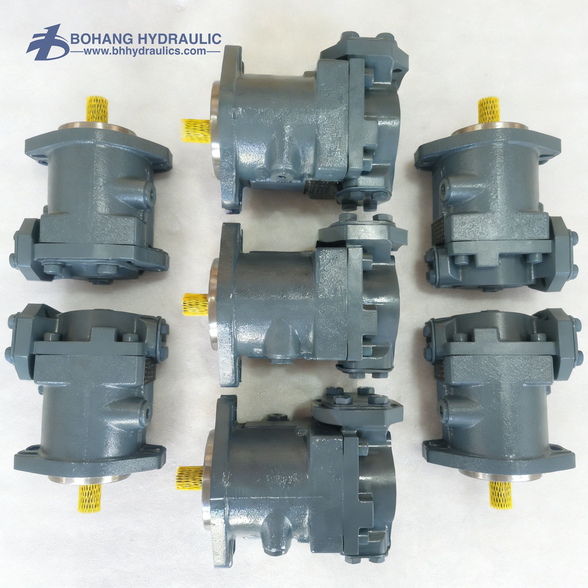
The A2FM fixed motor is available across a broad displacement range for open and closed circuits. The A6VM variable motor provides a wide control range, while the A6VE motor uses a plug-in form intended for compatible gearboxes. Ratings vary by size.
A variable motor increases the available speed and torque range, but it does not create additional power. Minimum displacement must be limited so that the motor does not exceed its permitted speed or operate with inadequate lubrication.
The A2FM is suited to fixed-displacement applications, while the A6VM provides a wider control range. The A6VE is intended for compact integration with compatible mechanical gearboxes.
How does a gearbox change the motor size?
A gearbox trades speed for torque. Assume the load needs 4,000 N·m at 80 rpm. With a 5:1 reduction and 94% gearbox efficiency:
Required motor torque = 4,000 ÷ (5 × 0.94) = 851 N·m
Required motor speed = 80 × 5 = 400 rpm
Without the gearbox, a much larger displacement motor or much higher pressure would be required. With too much reduction, the motor must run faster and may exceed its permissible speed.
Check gearbox input spline, pilot, lubrication, radial/axial loads, and allowable input speed. A plug-in motor should not be selected from displacement alone. In addition to ratio and efficiency, verify maximum gearbox input speed, spline capacity, lubrication, backlash and external shaft loads. Motor and gearbox interfaces must be checked as one complete drive assembly.
What pressure should I use in the calculation?
Use the pressure difference across the motor: Δp = inlet pressure − outlet pressure
For an open circuit with 250 bar inlet and 15 bar return pressure, Δp is 235 bar. For a closed circuit, measure both loop sides. During braking or reverse operation, the high-pressure side can change.
Use continuous pressure for continuous torque. Peak pressure covers short events only within the exact permitted duration and frequency.
Use gauges near both motor work ports whenever possible. Motor differential pressure is the inlet-port pressure minus the outlet-port pressure; case pressure is a separate limit and should not be included in this torque calculation.
How do I prevent overspeed?
Overspeed risk increases when:
- Load drives the motor faster than pump flow commands.
- A variable motor moves toward minimum displacement.
- A downhill or lowering load becomes overrunning.
- A hose fails or a valve opens unexpectedly.
- Pump flow exceeds the calculated limit.
Controls may include counterbalance or overcenter valves, displacement limits, speed sensing, pump-flow limits, braking valves, and mechanical brakes. The correct solution depends on the hazard analysis and circuit architecture.
For a variable motor, calculate maximum speed at minimum permitted displacement—not only at maximum displacement. Calculate maximum speed using the highest possible flow and the minimum permitted motor displacement. Overrunning loads may also drive the motor faster than commanded, so braking valves, charge flow, displacement limits or mechanical brakes may be required.
What if the calculation gives an awkward motor size?
The answer is not automatically “choose the next larger motor.” Compare four adjustments: gearbox ratio, permitted continuous pressure, variable-motor displacement range and pump flow. Each changes a different part of the duty cycle.
Using the earlier 122.3 L/min flow and 92% volumetric efficiency, a 250 cm³/rev motor is calculated near 450 rpm. A 280 cm³/rev motor at the same flow is about 402 rpm, while theoretical torque per bar rises by 12%. That may help a loaded conveyor but miss a travel-speed target. A small gearbox-ratio change may meet both points with less hydraulic oversizing.
Circuit architecture also affects the usable pressure and speed range. Review how open and closed circuits handle return flow, charge oil and braking. When an existing motor is being substituted, use the motor replacement interface checklist before accepting the calculated displacement. When hot speed is lower than predicted, a same-condition case-drain comparison can show whether leakage, rather than sizing, is the main problem.
Motor-sizing checklist
- Continuous load torque at the motor shaft
- Starting and peak torque with duration
- Normal and maximum speed
- Gear ratio and efficiency
- Available continuous and peak pressure difference
- Required flow at each operating point
- Maximum motor speed at minimum displacement
- Volumetric and mechanical efficiency assumptions
- Open or closed circuit
- Braking and overrunning-load behavior
- Case-drain routing and allowable case pressure
- Flushing requirement and cooling capacity
- Flange, pilot, shaft/spline, and port arrangement
- Control type, signal, and fail-safe position
- Oil viscosity and temperature range
Conclusion
Hydraulic motor sizing begins with the driven load, not the catalog. This guide explains how to calculate torque, speed, displacement, flow, and shaft power, then verify starting torque, duty points, pressure difference, efficiency and hot-oil performance. It also compares fixed and variable motors, shows how gearbox ratio affects motor size, and covers overspeed, braking, case pressure, mounting and replacement checks for reliable hydraulic drive selection under real-world operating conditions.
FAQ
Q1. Is pressure or flow more important when sizing a motor?
A: Both are required. Pressure difference determines the torque available from a selected displacement, while flow determines speed. A motor can have enough torque but remain too slow, or reach speed but lack torque. Size both operating axes and then check power, efficiency, and thermal duty.
Q2. Can I use nominal displacement as the exact displacement?
A: Use the geometric displacement published for the exact size when available. Nominal labels may be rounded. The difference may be small, but it affects speed and torque calculations, especially when the design has little margin or when pump and motor ratios control vehicle speed.
Q3. Why is actual torque lower than theoretical torque?
A: Mechanical friction, pressure losses, leakage-related effects, bearing loads, viscosity, temperature, and manufacturing condition reduce shaft torque. Starting efficiency can differ from running efficiency. Use mechanical-efficiency data for the operating point or apply a conservative assumption and verify on a test bench.
Q4. Can a larger motor solve low-torque problems?
A: A larger displacement increases torque per bar, but it also requires more flow for the same speed. Before changing size, confirm that low torque is not caused by low pressure differential, internal leakage, an unreleased brake, incorrect control displacement, or excessive mechanical load.