

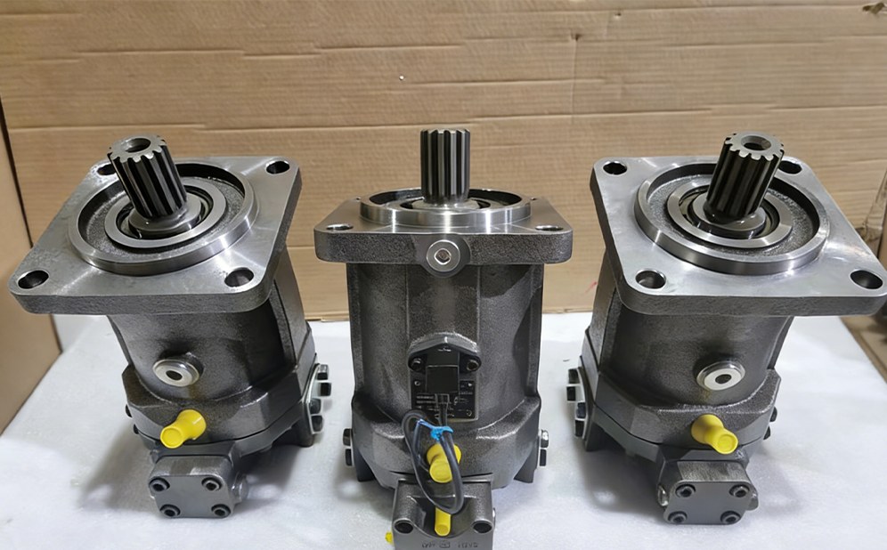
A pump–motor pair should be selected from the load backward. Starting with a pump already on the shelf and asking what motor it can run often produces a machine that moves but does not meet the required torque, speed, cooling, or service-life target.
Use this sequence:
- Define output torque and speed at the driven shaft.
- Include gearbox ratio and mechanical losses.
- Calculate the motor displacement and required flow.
- Calculate pump displacement from available drive speed.
- Check pressure, power, efficiency, and duty cycle.
- Verify the circuit, controls, interfaces, and commissioning requirements.
Practical answer: begin at the driven shaft. Calculate motor torque and speed first, convert them through the gearbox, then determine motor displacement, required flow, pump displacement and prime-mover power. Verify the result at start, continuous duty and maximum speed.
What must the driven machine actually do?
Collect data at the load, not only at the hydraulic ports.
- Required continuous torque
- Required breakaway or starting torque
- Normal and maximum speed
- Acceleration time
- Gearbox ratio and efficiency
- Duty cycle at each operating point
- Overrunning or braking load
- Ambient and oil-temperature range
- Available engine or electric-motor power
For a winch, starting torque and load holding may dominate. For a travel drive, acceleration and high-speed thermal duty can be more critical. For a fan or mixer, stable continuous speed may matter more than peak torque.
Which three operating points should I calculate?
Do not size from one rated point. Use at least three rows in the worksheet:
| Operating point | What usually controls the choice |
|---|---|
| Breakaway or acceleration | Starting torque, pressure rise, traction or load inertia |
| Continuous work | Thermal balance, continuous pressure, average efficiency |
| Maximum speed | Required flow, motor overspeed, charge and flushing capacity |
A unit can pass the continuous point and still stall at startup or overheat during transport. This three-point check is more useful than adding a large safety factor to one calculation.
How do I convert load torque to motor torque?
For a reduction gearbox: Motor torque = load torque ÷ (gear ratio × gearbox efficiency)
Assume a conveyor requires 4,800 N·m at 60 rpm. A 6:1 gearbox has 94% efficiency.
Motor torque = 4,800 ÷ (6 × 0.94) = 851 N·m
The motor speed must be: 60 × 6 = 360 rpm
Add a starting or shock factor only when the load data does not already include it. Applying multiple safety factors at different steps can oversize the system and create unnecessary heat. For a reliable hydraulic motor torque calculation, also check the gearbox’s rated input torque, motor shaft capacity, and low-speed starting efficiency. For reversing or overrunning loads, calculate both directions and include return-line pressure, because useful torque depends on the effective pressure difference across the motor ports.
What motor displacement is required?
Use: Displacement (cm³/rev) = required torque (N·m) × 62.83 ÷ [pressure difference (bar) × mechanical efficiency]
If the available continuous pressure difference is 250 bar and assumed motor mechanical efficiency is 90%: 851 × 62.83 ÷ (250 × 0.90) = 237.7 cm³/rev
A nominal 250 cm³/rev motor is a reasonable point for the next verification step. It is not a final selection until speed, maximum pressure, case pressure, control, and interface data are checked. For a separate check of starting torque, return pressure and overspeed, see how hydraulic motor size is calculated from torque and speed.
At 250 cm³/rev, 250 bar, and 90% mechanical efficiency, estimated shaft torque is: 250 × 250 × 0.90 ÷ 62.83 = 895 N·m
That provides modest margin above the calculated 851 N·m requirement.
How much flow is needed for the required speed?
For a motor: Required flow (L/min) = speed (rpm) × displacement (cm³/rev) ÷ [1,000 × volumetric efficiency]
At 360 rpm, 250 cm³/rev, and 92% volumetric efficiency: 360 × 250 ÷ (1,000 × 0.92) = 97.8 L/min
The valve, hoses, fittings, cooler, and charge/flushing circuit must handle this flow without creating unacceptable pressure loss. A pump rated for 100 L/min on a data sheet may deliver less at hot oil and working pressure.
When calculating hydraulic motor flow rate, use hot-oil volumetric efficiency rather than only the catalog’s nominal value. Add required flushing or charge flow separately, and confirm that valves, hoses, ports, and the cooler can pass the total circuit flow without excessive back pressure, heat, or speed loss.
How large should the pump be at the available drive speed?
Rearrange the pump-flow equation: Pump displacement (cm³/rev) = required flow (L/min) × 1,000 ÷ [pump speed (rpm) × pump volumetric efficiency]
Assume the pump turns at 1,800 rpm and estimated volumetric efficiency is 93%: 97.8 × 1,000 ÷ (1,800 × 0.93) = 58.4 cm³/rev
A variable pump with a maximum displacement near 60–63 cm³/rev could meet the point, subject to its pressure, speed, control, and power limits. If the pump is much larger, it must destroke accurately. If it is smaller, the motor cannot reach the target speed without reducing motor displacement or raising pump speed.
Will the engine or electric motor carry the load?
Hydraulic power at 250 bar and 97.8 L/min is: 250 × 97.8 ÷ 600 = 40.8 kW
At 87% overall pump efficiency, shaft input is approximately: 40.8 ÷ 0.87 = 46.9 kW
The prime mover needs additional margin for auxiliaries, acceleration, fan loads, and real operating temperature. For a diesel engine, verify torque at 1,800 rpm rather than relying on peak power at rated speed.
Motor output power can also be cross-checked: Output power (kW) = torque (N·m) × speed (rpm) ÷ 9,550
851 × 360 ÷ 9,550 = 32.1 kW
The difference between hydraulic input and mechanical output includes motor inefficiency, gearbox loss, and the conservative assumptions used in sizing.
What changes when both pump and motor are variable?
A variable pump and variable motor create a wide ratio range, but the controls must define where each component changes displacement. The control plan also depends on whether the machine uses an open or closed hydraulic circuit.
A common strategy is:
- Low vehicle speed: pump increases toward maximum displacement while the motor remains at high displacement for torque.
- Mid speed: pump reaches maximum displacement.
- Higher speed: motor reduces displacement to increase speed.
- Load increase: motor returns toward larger displacement and the pump/control system limits pressure or power.
The minimum motor displacement must be limited so the motor does not exceed its permitted speed. The control transition should be tested under load; a mismatched beginning-of-control pressure can cause jerking.
The A4VG closed-circuit pump is a relevant pump family for hydrostatic travel drives. The A6VM variable motor covers a broad control range, while the A2FM fixed motor is suited where motor displacement does not need to change. These are family-level examples; select the exact size and control code from the duty cycle.
Can the displacement ratio be treated like a gear ratio?
For a simplified loss-free closed loop: Motor speed ÷ pump speed ≈ pump displacement ÷ motor displacement
A 60 cm³/rev pump at 1,800 rpm driving a 250 cm³/rev motor gives: 1,800 × 60 ÷ 250 = 432 rpm theoretical
Using 93% pump volumetric efficiency and 92% motor volumetric efficiency: 432 × 0.93 × 0.92 = 369.5 rpm estimated
This aligns with the 360 rpm target. Leakage and charge-flow behavior change with pressure, temperature, and wear, so the measured ratio will vary.
The pump-to-motor displacement ratio is a useful sizing shortcut, not a fixed mechanical gear ratio. Actual motor speed changes with leakage, displacement command, oil temperature, charge flow, and loop pressure. Verify minimum motor displacement and maximum permitted speed before applying the ratio at high-speed operation.
Where should the design margin go?
Do not hide every uncertainty inside one oversized pump or motor. Keep separate allowances for uncertain load torque, hot-oil efficiency, acceleration and short pressure transients. That makes the reason for each margin visible and prevents the same risk from being counted twice.
At the worked flow of 97.8 L/min, a 10 bar pressure loss in lines and valves represents about 1.63 kW of continuous heat. Raising the relief setting does not recover that loss; it only increases stress elsewhere. Reduce avoidable restriction, confirm return pressure, and check the cooler before increasing displacement or pressure.
If the calculation is being used to replace an installed unit, verify the proposed frame, shaft, ports and control with the replacement compatibility checks used before ordering. If measured speed falls after the oil reaches operating temperature, compare the hot-oil result with a controlled pump and motor case-drain test before changing the calculated size.
Commissioning checklist
- Confirm motor and pump housings are filled as required.
- Verify rotation and hose connections at low risk.
- Start at minimum practical displacement and low pressure.
- Record charge pressure, case pressure, and oil temperature.
- Increase speed and load in steps.
- Measure actual pump flow, motor speed, and pressure differential.
- Check control transitions for hunting or shock.
- Confirm relief and power-control settings under controlled conditions.
- Inspect for aeration, noise, hose movement, and seal leakage.
- Save the baseline readings for future condition monitoring.
Conclusion
To match a hydraulic pump and motor, start with what the machine must do at the driven shaft—not with a pump already on the shelf. Define torque, speed, duty cycle and gearbox losses, then calculate motor displacement and flow before sizing the pump from available drive speed. Check startup, continuous duty and maximum speed separately, and confirm pressure, power, efficiency, cooling, controls and installation details. This load-first method helps avoid stalling, overheating and premature wear.
FAQ
Q1. Should pump and motor displacement be the same?
A: Not necessarily. Equal displacement gives an approximate 1:1 hydraulic speed ratio only when pump and motor speeds, leakage, and displacement settings align. Many drives intentionally use different displacements to create torque multiplication or speed reduction. Select the ratio from required motor speed, load torque, pump speed, and efficiency.
Q2. What happens if the motor displacement is too large?
A: A larger motor produces more torque per bar but requires more flow for the same speed. If pump flow is unchanged, the machine runs slower. The pump may also operate near maximum displacement for more of the duty cycle, reducing speed margin and potentially changing cooling or control behavior.
Q3. What happens if the motor displacement is too small?
A: A smaller motor turns faster at the same flow but produces less torque at the same pressure. The system may reach relief pressure without moving the load, and the motor may overspeed during light-load operation. Gearbox ratio and minimum variable-motor displacement must be checked together.
Q4. Do I size from peak pressure or continuous pressure?
A: Size continuous torque from the permitted continuous pressure and duty cycle. Peak pressure should cover short transients only when the exact product data defines the duration and frequency. Designing normal operation around peak pressure can raise temperature and reduce component life.