
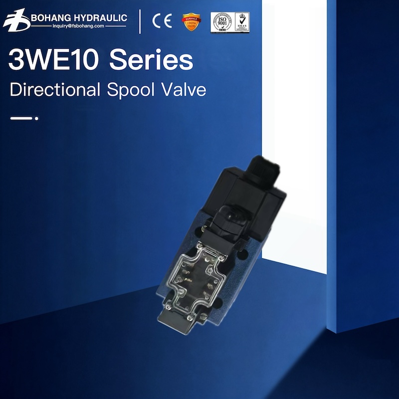
Hydraulic valves are components that control where hydraulic fluid goes, how much fluid moves, and how much pressure is allowed in a hydraulic circuit. By regulating direction, flow, and pressure, they determine whether a cylinder extends or retracts, how fast a hydraulic motor rotates, and whether the system remains within safe operating limits.
For engineers and equipment owners, the more useful question is not simply "What is a hydraulic valve?" but "Which valve function does my machine need?" This guide explains how hydraulic valves work, the most common types, how to match a valve to an application, and which problems to check when a hydraulic system does not perform as expected.
What Are Hydraulic Valves?
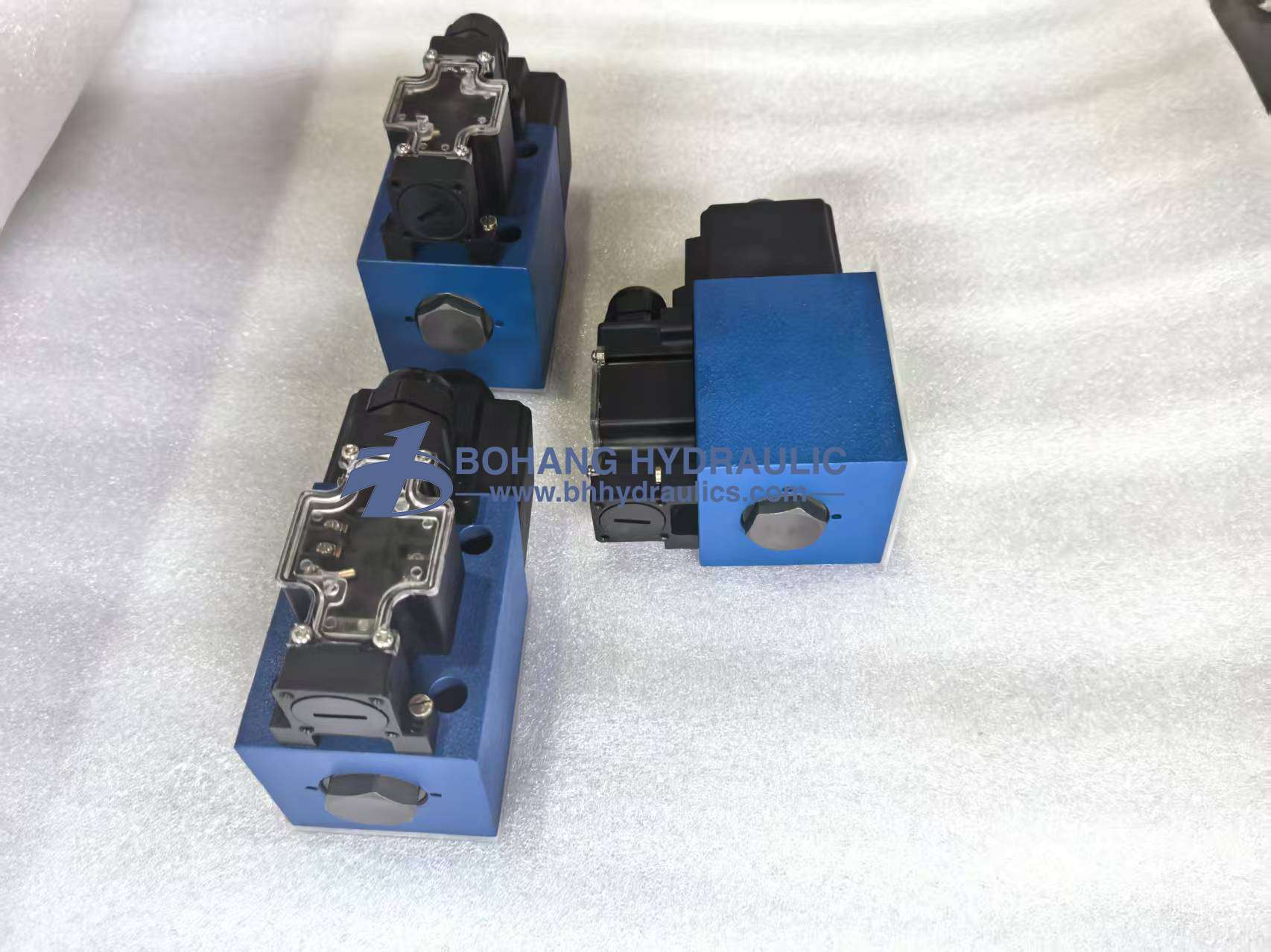
A hydraulic pump supplies fluid flow, while a cylinder or hydraulic motor converts hydraulic energy into movement. The valve sits between these components and controls how that energy is used.
A hydraulic valve performs one or more of three primary functions:
- Directional control: Routes fluid to start, stop, extend, retract, or reverse an actuator.
- Pressure control: Limits maximum pressure or maintains a required pressure in part of the circuit.
- Flow control: Adjusts the volume of fluid passing through the circuit and therefore influences actuator speed.
A valve does not create hydraulic power by itself. Instead, it opens, closes, diverts, or restricts passages so the available pump flow can perform the required work safely and predictably.
For example, when an excavator operator moves a control lever, a directional valve routes oil to one side of a cylinder. Oil from the opposite side returns to the tank. A pressure valve protects the system if the load becomes too high, while a flow-control function determines how quickly the boom moves.
How Do Hydraulic Valves Work?
Most hydraulic valves contain a movable control element, normally a spool, poppet, ball, or disc. Moving this element changes the connection between internal ports.
Depending on its position, the valve may:
- Open a passage and allow fluid to flow.
- Block a passage and stop fluid flow.
- Connect the pump port to an actuator port.
- Connect an actuator port to the tank.
- Restrict a passage to control flow.
- Open automatically when pressure reaches a preset value.
Flow Area and Pressure Drop
When a valve partially restricts a passage, fluid must pass through a smaller opening. This creates a pressure drop across the valve. The amount of pressure loss depends on factors such as flow rate, valve geometry, fluid viscosity, and spool position.
This is why a valve should not be selected only by thread or port size. Two valves with the same connection size can have very different flow capacities and pressure-drop characteristics.
An undersized valve may still operate the machine, but it can cause:
- Slow actuator movement
- Excessive heat generation
- Higher energy consumption
- Unstable response
- Shorter seal and fluid life
How Hydraulic Valves Are Actuated
A hydraulic valve can be shifted or controlled in several ways:
- Manual: A lever, knob, pedal, or handwheel moves the valve.
- Mechanical: A cam, roller, or machine movement actuates it.
- Solenoid-operated: An electromagnetic coil moves the spool or poppet.
- Hydraulically piloted: A small pilot-pressure signal controls a larger main stage.
- Electrohydraulic proportional: An electrical command positions the valve in proportion to the input signal.
- Servo-controlled: A high-response valve provides precise closed-loop motion control.
The correct actuation method depends on response time, flow capacity, automation requirements, available voltage, safety strategy, and operating environment.
Main Types of Hydraulic Valves
Hydraulic valves are usually classified by the function they perform. Directional, pressure, and flow control remain the three primary groups, but several important subtypes should be considered during system design or replacement.
1. Directional Control Valves
Directional control valves determine the path of hydraulic fluid. They are used to start, stop, or reverse cylinders and hydraulic motors.
Valve descriptions such as 2/2, 3/2, and 4/3 refer to the number of ports and spool positions:
- 2/2-way valve: Two ports and two positions, normally used for basic on/off control.
- 3/2-way valve: Three ports and two positions, commonly used with single-acting cylinders.
- 4/2-way valve: Four ports and two positions, used to reverse a double-acting actuator.
- 4/3-way valve: Four ports and three positions, providing extend, retract, and center states.
For a 4/3 valve, the center condition is as important as the number of ports. Open-center, closed-center, tandem-center, and float-center spools behave differently when the valve is in neutral.
Before replacing a directional valve, confirm:
- Number of ports and positions
- Spool symbol and center condition
- Solenoid voltage and connector type
- Spring-return or detented operation
- Rated flow and pressure
- Mounting interface
- Acceptable tank-port pressure
Choosing a valve only because it has the same external dimensions can result in unexpected actuator movement, pump loading, or poor load holding.
2. Pressure Control Valves
Pressure control valves manage force, protect components, and coordinate operations within a hydraulic circuit.
Common pressure-control valve types include:
Pressure Relief Valves
A relief valve limits maximum system pressure. When inlet pressure reaches the valve setting, it opens and diverts flow to the tank or another low-pressure path.
Relief valves provide essential overpressure protection, but they should not normally be used as continuous flow-control devices. When a relief valve remains open for long periods, hydraulic power is converted into heat.
Pressure-Reducing Valves
A pressure-reducing valve maintains a lower pressure in a branch circuit. It is useful when one actuator or control function requires less pressure than the main system.
Sequence Valves
A sequence valve allows a second operation to begin only after pressure in the first part of the circuit reaches a preset value. It can be used for processes such as clamp-then-press or lift-then-rotate.
Counterbalance Valves
A counterbalance valve helps control suspended or overrunning loads. It prevents a cylinder from moving faster than the incoming pump flow and reduces the risk of uncontrolled load descent.
Typical applications include cranes, lifting platforms, winches, booms, and vertically loaded cylinders.
Unloading Valves
An unloading valve sends pump flow to the tank at low pressure when hydraulic power is not required. This can reduce idle energy loss and heat generation in suitable circuit designs.
3. Flow Control Valves
Flow control valves regulate actuator speed by changing or maintaining the amount of fluid delivered to an actuator.
Common types include:
- Needle or throttle valves: Provide an adjustable restriction.
- Throttle-check valves: Restrict flow in one direction and allow freer flow in the opposite direction.
- Pressure-compensated flow valves: Maintain more consistent flow when load pressure changes.
- Priority valves: Reserve flow for a critical function before sending excess flow elsewhere.
- Flow-divider valves: Divide inlet flow between two or more circuit branches.
A basic throttle valve may be suitable when loads remain relatively constant. If the actuator load varies significantly and consistent speed is required, a pressure-compensated valve is generally more appropriate.
4. Check and Load-Holding Valves
A check valve permits flow in one direction and blocks reverse flow. It may be used to prevent backflow, maintain accumulator pressure, isolate circuit sections, or establish a preferred flow path.
A pilot-operated check valve can hold an actuator in position until pilot pressure deliberately releases it. However, a pilot-operated check valve and a counterbalance valve are not interchangeable in every load-control application. Dynamic or overrunning loads often require a properly selected counterbalance solution.
5. Proportional and Servo Valves
"Proportional" and "servo" describe how precisely the valve responds to a control command rather than a separate basic function. A proportional valve may control direction, pressure, or flow.
These valves are useful when the application requires:
- Variable speed rather than simple on/off movement
- Smooth acceleration and deceleration
- Repeatable pressure or force control
- Remote PLC control
- Closed-loop position, speed, or force control
The required accuracy should be balanced against fluid cleanliness, control electronics, commissioning complexity, and total system cost.
Structural Components of Hydraulic Valves
A high-quality hydraulic valve represents the culmination of materials science and precision machining. Leading hydraulic valve manufacturers invest significant resources in R&D and quality control for the following core components:
• Valve Body: Typically constructed from high-strength cast iron, forged steel, or aerospace-grade aluminum, designed to withstand extremely high internal pressures.
• Spool / Poppet (Control Element): The internal valve core, which undergoes heat treatment and ultra-precision grinding, with tolerances controlled at the micron level.
• Seals: Components that prevent internal and external leakage of high-pressure hydraulic fluid, thereby determining the valve's service life.
• Springs: Provide the mechanical restoring force and determine the pressure threshold at which the valve opens.
• Actuator: The mechanism that drives the valve, such as a solenoid coil or a manual control handle.
The seamless interplay of these precision components ensures that the hydraulic valve maintains stable regulatory performance even in extreme high-pressure environments—reaching 3000 PSI or higher. This is precisely where top-tier hydraulic pump manufacturers—along with their associated valve manufacturing partners—distinguish themselves from other industry players.
Applications of Hydraulic Valves
Any modern industrial setting requiring the "precise control of hydraulic power" relies heavily on the regulation provided by hydraulic valves.
1. Construction Machinery: The lifting of an excavator's boom or the precise hovering of a crane depends on the coordinated action of multi-way directional valves and proportional valves.
2. Industrial Manufacturing: From massive forging presses capable of exerting thousands of tons of force to high-precision injection molding machines, pressure valves and flow control valves ensure the flawless execution of forming processes.
3. Agricultural Equipment: Complex attachment control for heavy-duty tractors and combine harvesters.
4. Aerospace and Energy: Reliable retraction and extension of aircraft landing gear systems; precise angle adjustment for wind turbine pitch control systems.
When faced with extremely complex operating conditions, standard valves are often insufficient. This necessitates seeking *custom hydraulic solutions*—integrating multiple logic valves onto a single *custom manifold* to meet specific industrial requirements.
The Advantages of Hydraulic Valves
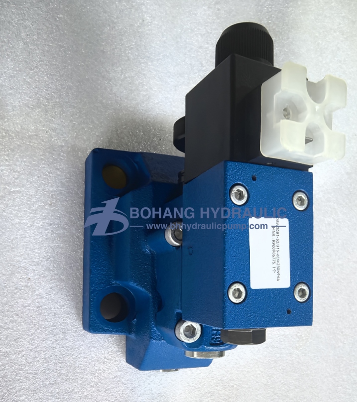
Advantages of Hydraulic Valves
Why do we invest so much effort in optimizing valve configurations during system design? Because they directly determine the upper limits of a machine's performance:
• Precise Control: Modern proportional and servo valves enable nearly flawless, stepless adjustment.
• Safety Protection: Pressure valves act as the system's "airbags," constantly guarding against overpressure and potential catastrophic failure.
• Enhanced Efficiency: Intelligent flow distribution can significantly reduce heat generation and energy loss within the system.
• Extended Lifespan: Smooth start-and-stop control drastically minimizes mechanical shock, thereby protecting both the pump and the actuators.
As mentioned earlier, if we were to anthropomorphize the system, the hydraulic valve would be the "brain"—constantly maintaining composure, thinking clearly, and issuing precise commands.
How to Select Hydraulic Valves
When consulting resources on *hydraulic valve selection* or proceeding with procurement, making the right choice is directly linked to the success or failure of your project. When considering *how to choose hydraulic valves*, be sure to prioritize the following core parameters:
1. Operating Pressure Range: The valve's rated pressure must exceed the system's maximum peak pressure.
2. Flow Requirements: The valve's nominal size (port diameter) must accommodate the system's maximum required flow rate (in Liters Per Minute/LPM) to prevent throttling-induced overheating.
3. Control Type: Clearly define whether you need to control direction, pressure, or flow rate.
4. Control Method: Depending on the machine's level of automation, choose between manual control or solenoid-actuated control compatible with a PLC.
5. Application Environment: For environments involving corrosive substances, high dust levels, or explosion-proof requirements, select valves featuring specialized protective coatings or relevant certifications.
Table 1: Key Parameters for Selecting Hydraulic Valves
| Selection Parameter | Technical Consideration | System Impact |
| Nominal Flow Rate | Internal port size and spool design. | Prevents excessive pressure drop and fluid overheating. |
| Maximum Pressure | Material strength of the valve body. | Ensures safety and prevents catastrophic physical failure. |
| Actuation Method | Solenoid, manual lever, or pneumatic. | Determines the system's level of automation and response time. |
| Fluid Compatibility | Viscosity limits and seal material (e.g., Viton/Nitrile). | Dictates internal lubrication effectiveness and seal longevity. |
Hydraulic Valves vs. Hydraulic Pumps vs. Hydraulic Motors
To clarify the system logic more effectively, we will compare the three core components of a hydraulic system:
Table 2: Logical Comparison of Core Components
| Component | Primary Function | Energy Conversion | Metaphorical Role |
| Hydraulic Pump | Supplies fluid power and flow. | Mechanical to Hydraulic | The "Heart" pumping the fluid. |
| Hydraulic Valves | Controls direction, flow, and pressure. | Directs and Regulates Energy | The "Brain" or "Nervous System". |
| Hydraulic Motor | Executes the final rotational movement. | Hydraulic to Mechanical | The "Muscles" performing the work. |
The core logic is evident: the pump is responsible for "power supply," the valve for "control," and the motor for "actuation." All three are indispensable.
FAQ
During the design and maintenance of hydraulic systems, engineers most frequently encounter the following questions:
1. What is the core function of hydraulic valves?
They are responsible for precisely controlling the flow direction of the hydraulic fluid within a closed-loop circuit, as well as regulating the system pressure and fluid flow rate.
2. How do hydraulic valves work?
They operate by physically displacing internal components (such as spools or poppets) to alter the cross-sectional area of the fluid passage, thereby modulating the flow state of the hydraulic fluid.
3. What are the most common types of hydraulic valves found in industry?
They are primarily categorized into three types: directional control valves, which govern flow paths; pressure control valves, which safeguard system safety; and flow control valves, which regulate the speed of motion.
4. Do hydraulic valves affect the overall efficiency of the system?
Yes, and the impact is significant. Improperly selected valves can induce severe localized pressure drops, causing hydraulic energy to dissipate as useless heat, thereby directly compromising the entire system's energy utilization efficiency and operational stability.
Conclusion
In summary, hydraulic valves are undoubtedly the most technologically sophisticated core control components within modern hydraulic systems. Their presence endows otherwise inert machinery with exceptional agility and precision.
Their core functions can be distilled into three key points: controlling flow to regulate speed; controlling pressure to ensure force and safety; and controlling direction to orchestrate mechanical movements.
When constructing industrial equipment, the proper selection of high-quality hydraulic valves not only determines the stability and safety of the system's operation but also directly impacts an enterprise's long-term maintenance costs and production efficiency. Whether you are seeking standard replacement control components or require the planning of a comprehensive, highly integrated custom solution, partnering with a technology provider possessing deep expertise and a solid track record is absolutely essential. If you are seeking high-performance hydraulic control products for your engineering equipment, we invite you to visit the official Bohang Product Center:
• Explore specialized control solutions: The BH Hydraulic Valves product series
• Discover complete system power components: The full range of BH Hydraulic products and solutions
We are committed to providing you with the most reliable fluid control capabilities, backed by state-of-the-art manufacturing processes.