

A hydraulic drive can reach the specified pressure and still feel weak. It can also run correctly when cold, slow down after twenty minutes, or accept a replacement that bolts on but responds badly to the machine controller. These failures happen because the pump, motor, circuit and load were checked as separate parts rather than as one power path.
Practical answer: select the pump and motor from the work the machine must perform, not from displacement alone. Flow sets motor speed, pressure difference supports torque, and the final result depends on efficiency, control behavior, oil temperature, circuit losses, and mechanical interfaces.
The gauge shows pressure, so why is the motor slow?
Pressure is created when flow meets resistance. It does not prove that the required volume is reaching the motor. Estimate pump delivery with:
Pump flow (L/min) = displacement (cm³/rev) × speed (rpm) × volumetric efficiency ÷ 1,000
A 71 cm³/rev pump at 1,800 rpm and 92% volumetric efficiency supplies about 117.6 L/min. If a 250 cm³/rev motor receives that flow at 92% motor volumetric efficiency, estimated speed is 433 rpm:
Motor speed (rpm) = flow × 1,000 × volumetric efficiency ÷ displacement
Measure actual pump speed, flow, oil temperature and motor case flow before blaming the motor. Hot oil can increase internal leakage, while an incorrectly adjusted pressure compensator or power control can keep a variable pump partly destroked.
How much torque should the motor produce?
Use pressure difference across the motor, not pump outlet pressure by itself:
Motor torque (N·m) = pressure difference (bar) × displacement (cm³/rev) × mechanical efficiency ÷ 62.83
At 250 bar pressure difference, 250 cm³/rev displacement and 90% mechanical efficiency, expected shaft torque is about 895 N·m. If return pressure is 20 bar and the supply gauge reads 250 bar, the useful difference is 230 bar, reducing the estimate to about 824 N·m.
Engineering view: calculate at three operating points—start or breakaway, normal continuous duty, and maximum speed. One “rated” point can hide a starting-torque problem or a high-speed cooling problem.
For a deeper calculation that includes gearbox ratio and overspeed checks, use the guide on sizing a hydraulic motor from torque and speed.
How do I match the pump to the motor without guessing?
Work backward from the driven shaft:
- Record continuous and starting torque, normal and maximum speed, acceleration time and duty cycle.
- Convert the load requirement through the gearbox ratio and gearbox efficiency.
- Select a motor displacement that meets torque at continuous pressure.
- Calculate the flow needed for motor speed.
- Calculate pump displacement from available prime-mover speed.
- Check pump input power, line losses, cooling and control range.
Hydraulic power is pressure × flow ÷ 600. At 250 bar and 100 L/min, hydraulic power is 41.7 kW. If pump overall efficiency is 87%, shaft input is about 47.9 kW before auxiliary loads. A diesel engine must be checked at the actual pump speed, not only at its advertised peak power.
The full worked pump-to-motor matching example shows how displacement ratio, efficiency and gearbox data affect the result.
Should this machine use an open circuit or a closed circuit?
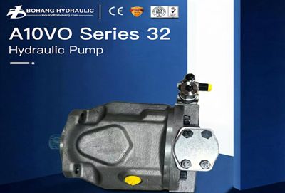
In the current pump range, the A10VO Variable Displacement Pump covers open-circuit duties from 18 to 140 cm³/rev, with 280 bar nominal and 350 bar peak pressure; the exact size and control code still need confirmation.
The A4VG Heavy Duty Variable Pumps covers closed-circuit sizes from 28 to 125 cm³/rev, with 400 bar nominal and 450 bar peak pressure.
Do not confuse open circuit with open-center valve. One describes the main oil path; the other describes what a directional valve does in neutral. The comparison of open and closed hydraulic circuits explains charge pressure, flushing and overrunning loads.
Fixed or variable displacement—which is safer?
A fixed-displacement unit reduces control complexity and can suit steady-speed functions. A variable pump can match flow to demand, and a variable motor can extend the speed–torque range. The wider ratio is useful, but only when the control sequence, minimum motor displacement and maximum motor speed are defined.
For example, the current range includes A2FM fixed motors and A6VM variable motors across broad displacement ranges, while A6VE provides a plug-in variable arrangement for compatible gearboxes. Product-family ranges are a screening tool, not a substitute for the full type code and exact performance data.
Which measurement should I take before removing the unit?
| Symptom | Measure first | Likely directions |
|---|---|---|
| Slow at all temperatures | Pump speed, delivered flow, motor displacement command | Undersized pump, destroking, valve restriction, wrong control |
| Strong cold, weak hot | Hot-oil flow and case-drain trend | Internal leakage, low viscosity, worn rotating group |
| Noise at pump inlet | Inlet vacuum, oil level, temperature | Restriction, air entry, unsuitable viscosity |
| High temperature | Pressure drop and flow across valves or bypass paths | Throttling loss, relief flow, inadequate flushing or cooling |
| Seal leakage | Case pressure and drain restriction | Blocked, undersized or incorrectly routed case line |
A controlled case-drain test under hot operating conditions can indicate rising internal leakage. Never cap the drain line, and do not apply a universal pass/fail flow number.
The replacement fits—what else can still be wrong?
Compatibility has three layers:
- Mechanical: flange pilot, bolt pattern, shaft or spline, coupling engagement and alignment.
- Hydraulic: displacement, rotation, pressure class, port positions, case pressure, circuit type and oil compatibility.
- Control: regulator type, setting range, pilot supply, solenoid voltage, connector and signal logic.
After a destructive failure, inspect the reservoir, cooler, filters, hoses and valve blocks for debris before installing a new unit. Filling a clean replacement from a contaminated circuit can cause another failure before meaningful commissioning data is collected. Use the pump and motor replacement compatibility checklist before an order is released.
Which limit should decide the final selection?
A useful way to review a pump–motor system is to draw three overlapping envelopes. The work envelope contains starting torque, continuous torque, speed and acceleration. The hydraulic envelope contains usable pressure difference, hot-oil flow, input power, case pressure and cooling capacity. The installation envelope contains circuit type, controls, shaft, flange, ports and available space. A component is suitable only where all three overlap. Record the source of every input as measured, calculated, assumed, or taken from a family page. That label makes the review auditable and shows which value should be tested first when the machine does not meet the predicted speed, torque, or temperature.
This prevents a common mistake: treating pressure at the pump as pressure available at the motor. If a system delivers 100 L/min and loses 12 bar through valves, hoses and fittings, about 2.0 kW is converted to heat before the motor because loss power equals pressure drop × flow ÷ 600. If the return line adds another 18 bar, motor torque must be calculated from the remaining pressure difference, not from the pump gauge alone.
Our engineering view: use product-family figures to shortlist a unit, then approve the exact type code against the duty cycle. The current range includes open-circuit A10VO pumps at 18–140 cm³/rev and closed-circuit A4VG pumps at 28–125 cm³/rev, but control code, speed limit and size-specific ratings still decide the final fit.
Selection checklist for an engineer or buyer
- Load torque, speed range, acceleration and duty cycle recorded
- Continuous and peak pressure kept separate
- Return pressure included in motor pressure difference
- Hot-oil efficiency assumptions documented
- Prime-mover power checked at actual operating speed
- Open or closed circuit confirmed from the schematic
- Full model code, rotation, shaft, flange, ports and controls verified
- Case-drain route and permitted case pressure checked
- Contamination-control and startup plan approved
Conclusion
Hydraulic pump and motor selection should begin with the machine's required torque, speed, acceleration and duty cycle. Flow determines motor speed, while usable pressure difference produces torque. Reliable sizing must also account for efficiency, oil temperature, circuit losses, gearbox data, prime-mover power, cooling and control range. Open or closed circuit design, case-drain condition, mounting details, full model codes and proper commissioning all affect final drive performance over time.
FAQ
Q1. Does higher hydraulic pressure make a motor run faster?
A: No. Pressure difference mainly determines available motor torque, while flow and motor displacement determine speed. A motor may be slow even when the system reaches relief pressure because pump flow is low, a valve is restricting flow, the pump is destroked, or internal leakage increases after the oil warms.
Q2. Should pump and motor displacement be the same?
A: Not necessarily. Equal displacement gives an approximate one-to-one hydraulic speed ratio only in a simplified system. Real selection starts with required load torque and speed, then includes pump speed, gearbox ratio, volumetric efficiency, mechanical efficiency, control range, and continuous pressure limits.
Q3. How do I choose between an open and closed hydraulic circuit?
A: Choose from the machine function. Open circuits are practical when a reservoir and valve bank serve several actuators. Closed circuits suit compact bidirectional hydrostatic drives, but they require charge flow, flushing, cooling, and low-side pressure control. Open circuit is not the same term as open-center valving.
Q4. How much case-drain flow is acceptable?
A: There is no reliable universal number. Compare the measured flow with the exact unit limit or a known-good baseline at the same oil temperature, speed, displacement, pressure, and case pressure. A rising hot-oil trend is usually more useful than one isolated reading at idle.
Q5. What information is needed to quote a replacement pump or motor?
A: Provide the complete model code, readable nameplate photos, displacement, rotation, flange, shaft or spline, port arrangement, control code, circuit type, pressure range, machine model, oil type, and failure symptoms. The short family name alone rarely identifies a compatible configuration.