
Hydraulic Valves
 Hydraulic Valves

4WRTE100 Series High-Performance Proportional Directional Control Valves

Features : 

▶ Reliable – proven and robust design
▶ Safe
– Automatic pressure compensation in the control
chambers of the main stage by the pilot control 
valve
– Control spool of the main stage in the springcentered central position and/or in the offset 
position
– Optionally with spool position monitoring
▶ Flexible – suitable for position, speed and pressure
control
▶ Precise – high response sensitivity and little hysteresis            
▶ Size 10 … 35
▶ Component series 4X
▶ Maximum operating pressure 350 bar
▶ Rated flow 25 … 1000 l/min

4WRTE100 proportional directional valve provides hydraulic control for position, speed and pressure applications, with automatic pressure compensation, up to 350 bar pressure and flows from 25 to 1000 L/min. High response sensitivity suits injection moulding machines, presses, cranes, metal forming equipment and mobile machinery, helping address motion errors, pressure fluctuation, uneven cycles and commissioning delays in production systems.

1. Spring Centered or Offset Spool: Supports neutral or offset rest positions to match different actuator circuit designs.
2. Optional Spool Position Monitoring: Provides feedback for diagnostics, process supervision and control verification.
3. NG10 to NG35 Size Options: Makes it easier to match valve dimensions with machine scale and manifold requirements.
4. Internal or External Pilot Return: Allows the pilot circuit to be configured according to tank layout and return pressure conditions.
5. Wide Viscosity Compatibility: Supports hydraulic oil viscosities from 20 to 380 mm²/s for varied operating conditions.

FAQ

Q1. Is the 4WRTE100 a proportional pressure relief valve?
A:
No. The 4WRTE100 is a proportional directional control valve. It regulates actuator direction and continuously variable movement, while a proportional relief valve is mainly used to limit or adjust system pressure. The 4WRTE100 can support pressure control applications when combined with suitable sensors, feedback and electronic control, but it should not replace the main safety relief valve.
Q2. Why does the hydraulic system show pressure fluctuation or unstable movement?
A:
Common causes include unsuitable amplifier gain, noisy command signals, unstable pilot pressure, incorrect spool selection, air in the oil, contamination or excessive valve sizing. Check the control parameters and pilot circuit first, then verify oil cleanliness and the valve's pressure and flow conditions.
Q3. How should I choose the correct 4WRTE100 valve size?
A:
Start with the actuator's required flow and working pressure. Then compare the rated flow, valve size, spool symbol, pressure drop, pilot flow and mounting dimensions. Do not select only by port size. The 4WRTE series covers NG10 to NG35, so the complete model code and technical data sheet should be checked before ordering.
Q4. Can this valve be used for injection molding machines or hydraulic presses?
A:
It can be considered for these applications when the required pressure, flow, spool function, electronic signal, mounting arrangement and oil conditions are suitable. Its proportional control is useful where the machine needs smoother actuator movement, repeatable cycles or coordinated pressure and speed control.
general
Sizes NG 10  16  25  27  32  35 
Weight kg 8.7  11.2  16.8  17  31.5  34 
Installation position and commissioning information Preferably horizontal, see data sheet 07700
Ambient temperature range °C –20 … +50
Maximum storage time Years 1 (if the storage conditions are observed; refer to the operating
    instructions 07600-B)
MTTFD values according to EN ISO 13849 Years 150 1)  (for more information see data sheet 08012)
Sine test according to DIN EN 60068-2-6   10 ... 2000 Hz / maximum of 10 g / 10 cycles / 3 axes
Noise test according to DIN EN 60068-2-64   20 … 2000 Hz / 10 gRMS / 30 g peak / 30 min. / 3 axes
Transport shock according to DIN EN 60068-2-27   15 g / 11 ms / 3 shocks / 3 axes
Damp heat, cyclic, according to DIN EN 60068-2-30  

Variant 2
+25 °C … +55 °C, 90% … 97% relative humidity, 2 cycles of
24 hours


hydraulic
Sizes                                                                                                NG 10  16  25  27  32  35 
Maximum               ▶ Pilot control valve   Pilot oil supply 2)                        bar
operating pressure   ▶ Main valve             Port P, A, B                        bar
25 … 315
350  350  350  270  350  350 
Maximum return
flow pressure
▶ Port T        Internal pilot oil return     bar
                          External pilot oil return     bar
▶ Port Y                                                                bar
Static < 10
315  250  250  210  250  250 
Static < 10
Rated flow qVnom ±10% 3)                                l/min 25  150  – – – –
with Δp = 5 bar/control edge 50
100
–
220
220
350
–
500
400
600
–
1000
Maximum flow (recommended)                   l/min 170  460  870  1000  1600  3000 
Pilot oil flow at port X or Y with stepped
input signal from 0 to 100% (315 bar)
l/min 7  14  20  20  27  29 
Pilot oil volume 0 … 100%           cm³ 1.1  2.9  6.8  6.8  17.7  33.9 
Hydraulic fluid See table below
Hydraulic fluid temperature range
(at the valve working ports)
°C –20 ... +80; preferably +40 … +80
Viscosity range                    mm2/s 20 ... 380; preferably 30 ... 45
Maximum admissible degree of contamination of the hydraulic fluid,
cleanliness class according to ISO 4406 (c)
Class 18/16/13 4)
Hysteresis                       % ≤ 0.1
Response sensitivity       % ≤ 0.05
Zero point calibration (ex works) 5)             % ≤ 1
Temperature drift                %/10 °C Zero shift < 0.3
  Machine Hydraulci Pump/Motor
Construction Machinery
Concrete mixer AA2FM A4VTG EATON 5423        
Concrete transport pump A2FO A4VG A11V        
Wet spraying machine A11V A2FM A10V        
Road roller A6VE A6VM  A4VTG P2VC      
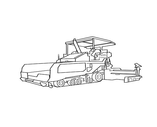
Paver A6VE A6VM  P2VC P4VC      
Grader A6VM  P2VC          
Asphalt spreader P1V(A)O A2FM          
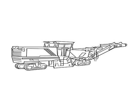
Milling machine P1V(A)O A2FE A2FM        
Crawler excavator P3VO            
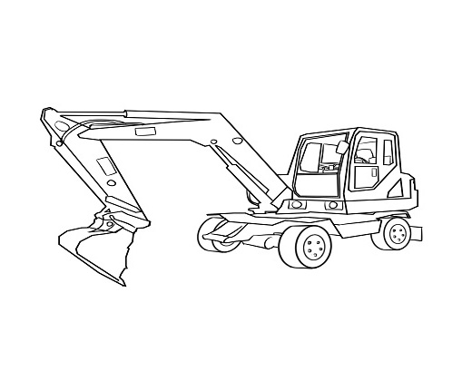
Wheel excavator A6V A6VM  P3VO        
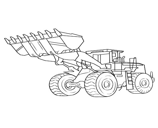
Loader M3VE A6VM  P2VC A10VSO A2FM    
Bulldozer A6VM  P2VC          
Material Handling Machinery
Crane A2FE A6V A6VM P2VC P1V(A)O A10VSO A2FM
Forklift              
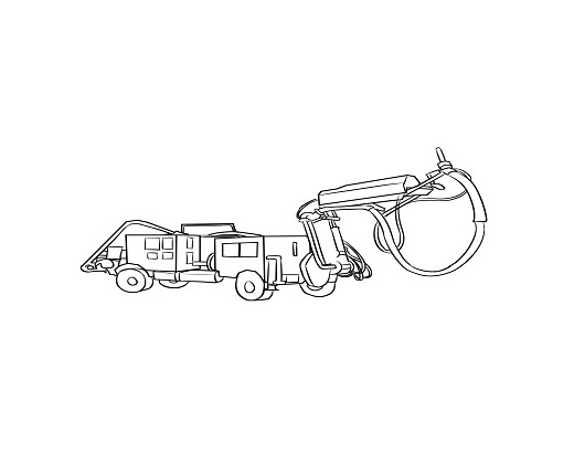
Drilling Rig A2FE A6VE A6VM P1V(A)O A10VSO A2FM  
Heading Machine A2FE P1V(A)O          
Mining Truck A10VSO            
Agricultural Machinery
Tractor A6VE P2VC P4VC A10VSO      
 Rice Transplanter              
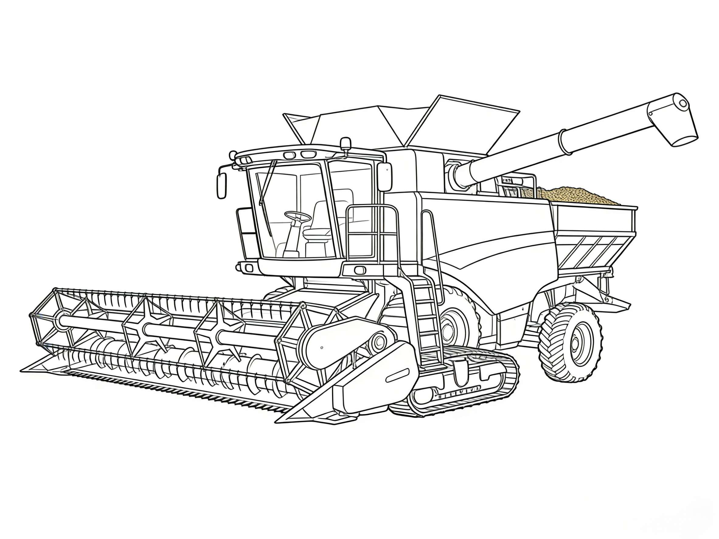
Combine Harvester A6VE A4VTG P2VC        
Pesticide machine A6VE A4VTG P2VC A10VSO      
Rice harvester A6VE A4VTG P2VC P4VC      
Sugar Cane Harvester A6VE P2VC P4VC A10VSO A2FM    
Municipal Machinery
Airport Equipment A6VM P2VC P1V(A)C A10VSO A2FE A2FM  
Firfighting Truck A7VO P1V(A)C A10VSO        
Snow Sweeper P2VC A10VSO          
Aerial work platform P4VC A10VSO          
Electric Power A2FE A6VE P2VC P4VC      
Environmental Sanitation Vehicle              
Anti Dust Vehicle              
Oil And Gas Equipment
Liquid Nitrogen Pump Truck P1V(A)O            
Fracturing Truck A6VM P2VC A2FO A2FM      
Fracturing Blender Truck A6VM P2VC A10VSO A2FM      
Coil Tubing A10VSO A2FE          
Pipelayer A2FE A6VM P1V(A)O        
Industrial Application
Injection molding machine              
Shoe-making machine A10VSO            
Metal forming machinery A7V            
CNC machine tool PV A10VSO          
Metallurgy and die-casting E-A4VG             
Flow Machine
Reach Stacker P3VO            
Heavy Forlift A6VM A4VTG A10VSO        
Tire Crane A6VM            
Maritime Port
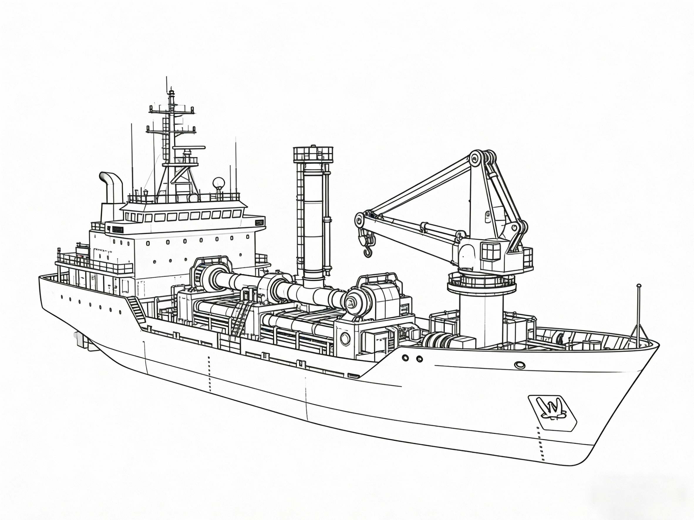
Ship A6VE A6VM P1V(A)O A10VSO A2FE A2FM  
Offshore platform A6VE A6VM P1V(A)O A10VSO A2FE A2FM  
Wind power P1V(A)O            
Dredging vessels P1V(A)O            
Others              
Marine Crane A 11VLO A2FM FMF  A4VG A6VM