
Hydraulic Valves
 Hydraulic Valves

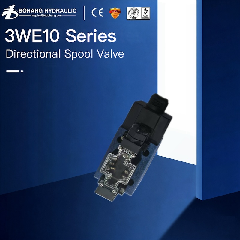
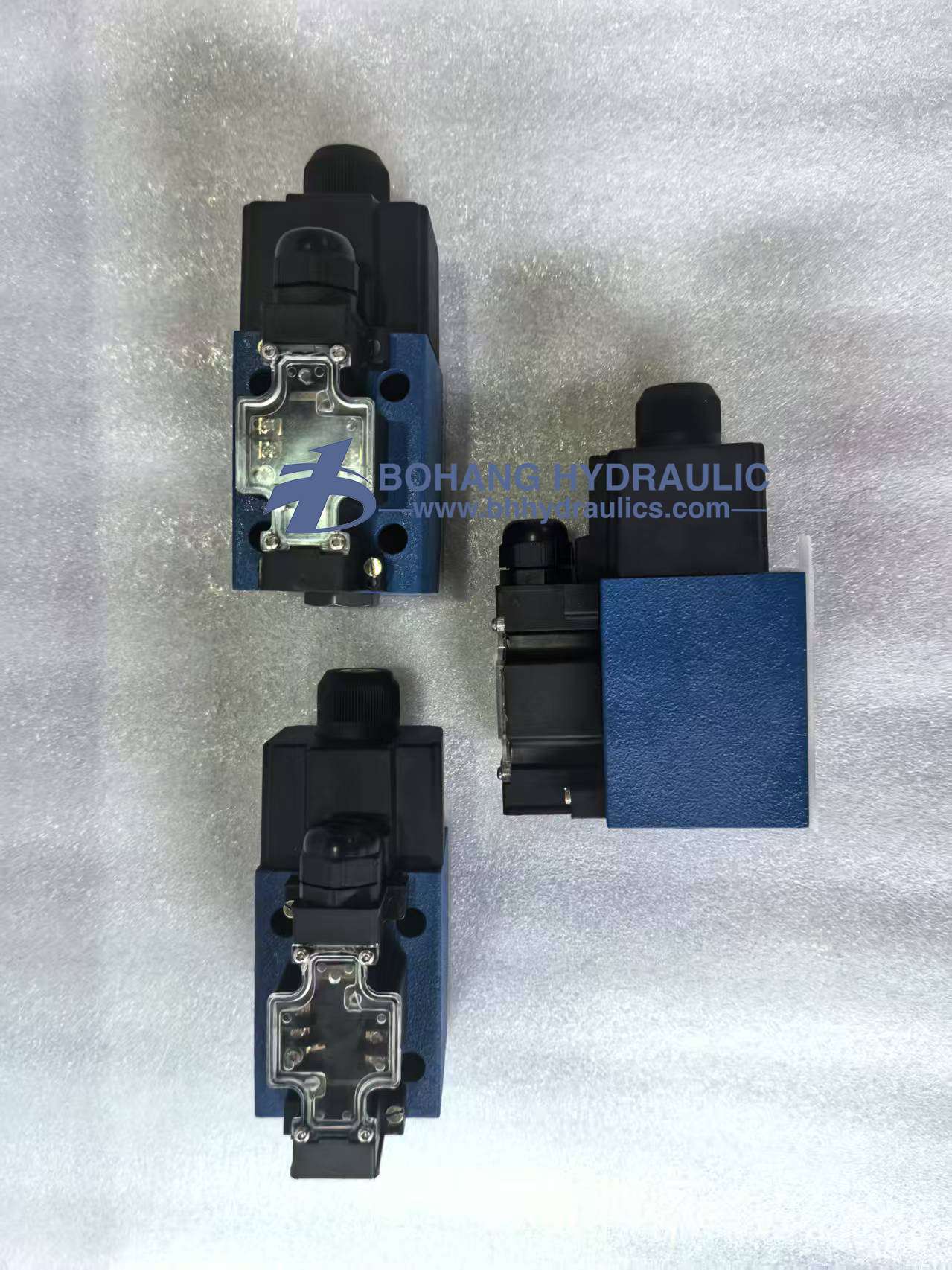
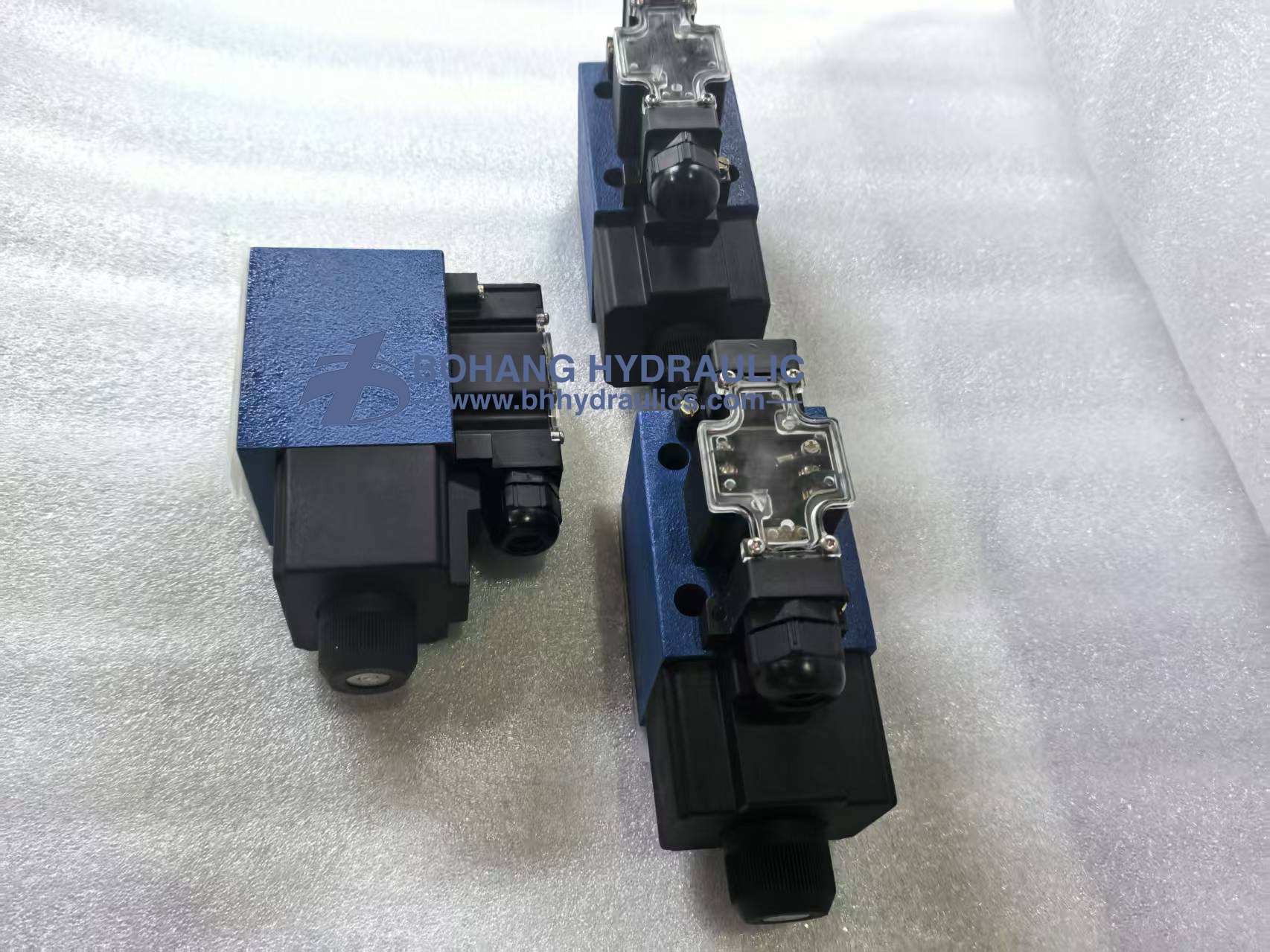
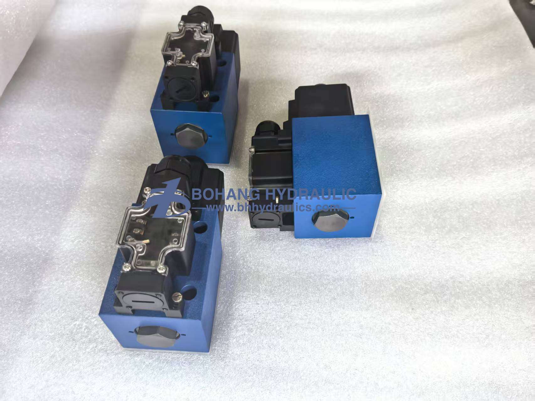
3WE10 Series Replacement Directional Spool Valves

Features :
▶ 4/3-, 4/2- or 3/2-way version
▶ Porting pattern according to ISO 4401-05-04-0-05
and NFPA T3.5.1 R2-2002 D05
▶ High-power solenoid, optionally rotatable by 90°
▶ Electrical connection as individual connection
▶ Cartridge optionally equipped with PWM connector 
(fast switching amplifier, energy reduction)
▶ Manual override, optional
▶ Spool position monitoring, optional
▶ CE conformity according to the Low-Voltage Directive 
2006/95/EC for electrical voltages > 50 VAC or > 75 VDC
▶ Solenoid coil with UR approval UL 429
▶ Approval according to CSA C22.2 No. 139-10, optional                  
▶ 5-chamber version
▶ Size 10
▶ Component series 5X
▶ Maximum operating pressure 420 bar [6091 psi]
▶ Maximum flow 150 l/min [39.6 US gpm]

3WE10 Series Replacement Directional Spool Valve provides dependable flow direction control for mobile and industrial hydraulic equipment. Supporting up to 420 bar and 150 L/min, it helps solve slow actuator movement, drifting, oil overheating and unplanned downtime caused by worn valves. Standardized mounting and selectable switching options simplify retrofits, helping maintenance teams restore hydraulic performance in demanding environments.


1. 90°-Rotatable Solenoid: Reorient the coil for easier access inside compact hydraulic systems.

2. PWM Energy-Saving Option: Support faster switching and reduced electrical consumption with an optional PWM connector.

3. Manual Override Option: Enable functional checks and emergency operation during commissioning or power loss.

4. Spool Position Monitoring: Verify actual spool movement and improve troubleshooting efficiency with optional feedback.

5. Compliance-Ready Coil Selection: CE conformity, UR-approved coils and optional CSA approval support international equipment requirements.


FAQ

Q1: How do I choose the correct replacement 3WE10 directional spool valve?

A: Match the valve function, spool symbol, mounting pattern, actual system flow, working pressure, coil voltage, connector, spring-return or detent design, seal material and T-port back-pressure limit. A valve with the same size may still operate differently if its spool center function is incorrect.

Q2: Why does the solenoid click but the hydraulic cylinder does not move?

A: Check coil voltage under load, wiring, connector condition, manual override operation, pump pressure, return-line back pressure and spool contamination. If the manual override shifts the valve but the electrical command does not, inspect the coil and control circuit. If neither method shifts the spool, check for internal sticking or mechanical damage.

Q3: Why is my actuator moving slowly or drifting after valve replacement?

A: Excessive internal leakage may result from spool or bore wear, contaminated oil or an incorrect spool configuration. Slow cycles and actuator drift are common symptoms. Inspect the valve and hydraulic oil, verify the spool symbol, and replace the valve if internal wear is confirmed.

Q4: Why does hydraulic oil become hot after installing a new directional valve?

A: The new valve may have excessive pressure drop, an incorrect neutral position, an undersized flow passage or excessive return back pressure. The relief valve may also be bypassing continuously. Check pressure before and after the valve and verify the neutral flow path before changing the cooler.

Q5: What causes a hydraulic directional spool valve to leak?

A: External leakage can come from damaged seals, spool wear, push-pin wear or a solenoid core tube. Internal leakage is commonly related to worn spool-to-bore clearance or contaminated oil. Replace damaged seals where appropriate, but replace the complete valve when internal wear causes unacceptable leakage.

Q6: Will the 3WE10 valve fit my existing manifold?

A: The 3WE10 series uses an ISO 4401-05-04-0-05 and NFPA D05 mounting pattern, but installation compatibility also depends on the spool symbol, port arrangement, dimensions, pressure, flow, coil voltage and connector. Send the old valve model, nameplate, photos, hydraulic symbol and machine operating data before ordering.
general
Weight                     ▶ Valve with one solenoid
                             ▶ Valve with two solenoids
kg [lbs] 3.9 [8.6]
kg [lbs] 5.5 [12.1]
Installation position   Any 1)
Ambient tempera-     ▶ Standard version °C [°F] –20 … +70 [–4 … +158] (NBR seals)
ture range
                             ▶ Version for HFC hydraulic fluid
                             ▶ Low-temperature version 2)
  –15 … +70 [+5 … +158] (FKM seals)
°C [°F] –20 … +50 [–4 … +122]
°C [°F] –40 … +50 [–4 … +122]
Storage temperature range °C [°F] –20 … +50 [–4 … +122]
MTTFd values according to EN ISO 13849 Years 300 (for further details see data sheet 08012)
     
hydraulic
Maximum operating pressure
(pP  > pA; pB  > pT)
▶ Port A, B, P                           bar [psi]
▶ Port T                                   bar [psi]
350 [5076]; 420 [6091]
210 [3050]      Tank pressure (standard)
With symbols A and B, port T must be used as leakage oil con-
nection if the operating pressure exceeds the maximum admissi-
ble tank pressure.
Maximum flow l/min [USgpm] 150 [39.6]
Flow cross-section
(spool position 0)
   ▶ Symbol Q
   ▶ Symbol W
mm2 Approx. 6 % of nominal cross-section
mm2 Approx. 3 % of nominal cross-section
Hydraulic fluid   See table below
Hydraulic fluid temperature range
(at the valve working ports)
°C [°F] –20 … +80 [–4 … +176] (NBR seals)
–15 … +80 [+5 … +176] (FKM seals)
–20 … +50 [–4 … +122] (HFC hydraulic fluid)
–40 … +50 [–4 … +122] (Low-temperature version)
Viscosity range mm2/s [SUS] 2.8 … 500 [35 … 2320]
Maximum admissible degree of contamination of the
cleanliness class according to ISO 4406 (c)
hydraulic fluid Class 20/18/15 3)
  Machine Hydraulci Pump/Motor
Construction Machinery
Concrete mixer AA2FM A4VTG EATON 5423        
Concrete transport pump A2FO A4VG A11V        
Wet spraying machine A11V A2FM A10V        
Road roller A6VE A6VM  A4VTG P2VC      
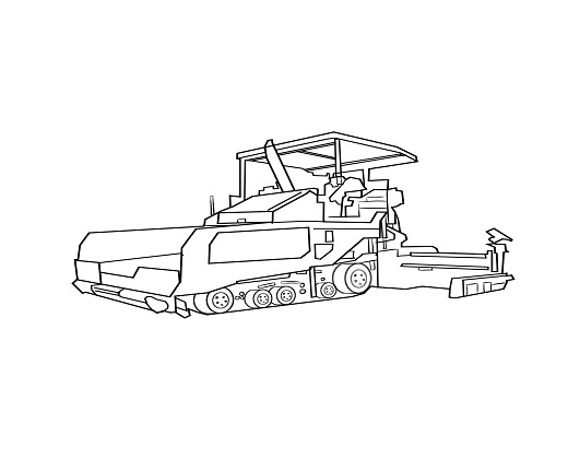
Paver A6VE A6VM  P2VC P4VC      
Grader A6VM  P2VC          
Asphalt spreader P1V(A)O A2FM          
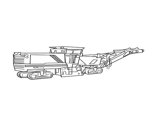
Milling machine P1V(A)O A2FE A2FM        
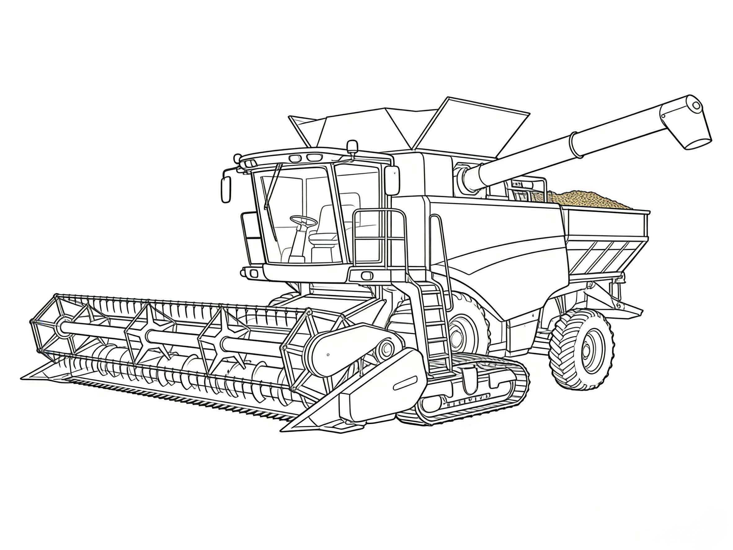
Crawler excavator P3VO            
Wheel excavator A6V A6VM  P3VO        
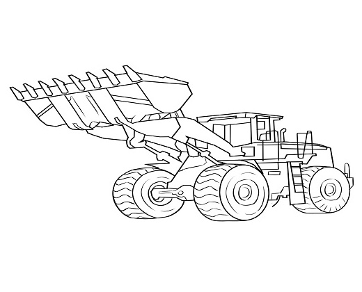
Loader M3VE A6VM  P2VC A10VSO A2FM    
Bulldozer A6VM  P2VC          
Material Handling Machinery
Crane A2FE A6V A6VM P2VC P1V(A)O A10VSO A2FM
Forklift              
Drilling Rig A2FE A6VE A6VM P1V(A)O A10VSO A2FM  
Heading Machine A2FE P1V(A)O          
Mining Truck A10VSO            
Agricultural Machinery
Tractor A6VE P2VC P4VC A10VSO      
 Rice Transplanter              
Combine Harvester A6VE A4VTG P2VC        
Pesticide machine A6VE A4VTG P2VC A10VSO      
Rice harvester A6VE A4VTG P2VC P4VC      
Sugar Cane Harvester A6VE P2VC P4VC A10VSO A2FM    
Municipal Machinery
Airport Equipment A6VM P2VC P1V(A)C A10VSO A2FE A2FM  
Firfighting Truck A7VO P1V(A)C A10VSO        
Snow Sweeper P2VC A10VSO          
Aerial work platform P4VC A10VSO          
Electric Power A2FE A6VE P2VC P4VC      
Environmental Sanitation Vehicle              
Anti Dust Vehicle              
Oil And Gas Equipment
Liquid Nitrogen Pump Truck P1V(A)O            
Fracturing Truck A6VM P2VC A2FO A2FM      
Fracturing Blender Truck A6VM P2VC A10VSO A2FM      
Coil Tubing A10VSO A2FE          
Pipelayer A2FE A6VM P1V(A)O        
Industrial Application
Injection molding machine              
Shoe-making machine A10VSO            
Metal forming machinery A7V            
CNC machine tool PV A10VSO          
Metallurgy and die-casting E-A4VG             
Flow Machine
Reach Stacker P3VO            
Heavy Forlift A6VM A4VTG A10VSO        
Tire Crane A6VM            
Maritime Port
Ship A6VE A6VM P1V(A)O A10VSO A2FE A2FM  
Offshore platform A6VE A6VM P1V(A)O A10VSO A2FE A2FM  
Wind power P1V(A)O            
Dredging vessels P1V(A)O            
Others              
Marine Crane A 11VLO A2FM FMF  A4VG A6VM