
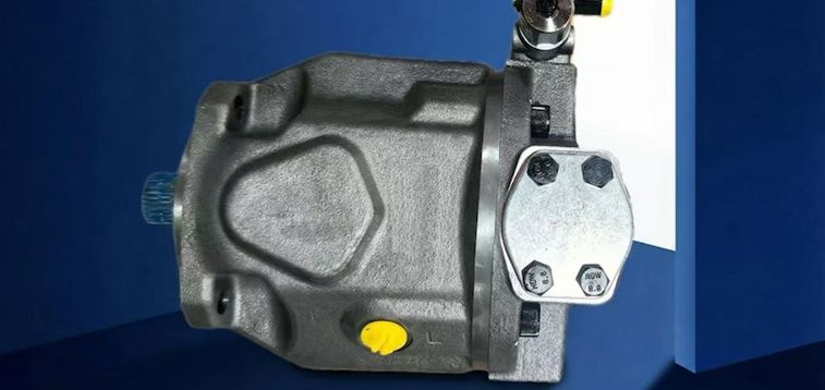
A hydraulic pump is the component that puts hydraulic fluid into motion. It receives mechanical power from an electric motor, diesel engine, PTO or another prime mover and converts that input into hydraulic flow. When the oil meets resistance from a cylinder, hydraulic motor, valve or load, pressure develops and the system can lift, push, clamp, steer or rotate equipment.
In simple terms: The pump moves the oil. Resistance creates pressure. The actuator turns that hydraulic energy into useful work.
This distinction matters. A pump should not be selected only because it has a high pressure rating. It must deliver the right flow at the required pressure, speed, temperature and duty cycle without creating excessive heat, noise or wear.
What Does a Hydraulic Pump Actually Do?
A hydraulic pump performs four basic jobs:
- It receives mechanical input through its drive shaft.
- It creates expanding chambers at the inlet, reducing inlet pressure so oil can enter from the reservoir.
- It traps and carries a measured volume of oil through the pump.
- It displaces that oil into the hydraulic circuit to power cylinders and motors.
Most pumps used in industrial and mobile hydraulic systems are positive displacement pumps. A fixed displacement pump moves approximately the same theoretical volume during each shaft revolution. A variable displacement pump changes its output by adjusting the geometry of the pumping group.
The pump is only one part of the energy transfer process. Valves direct and regulate the oil. Cylinders convert hydraulic energy into linear force and movement. Hydraulic motors convert hydraulic energy into rotary torque and speed.
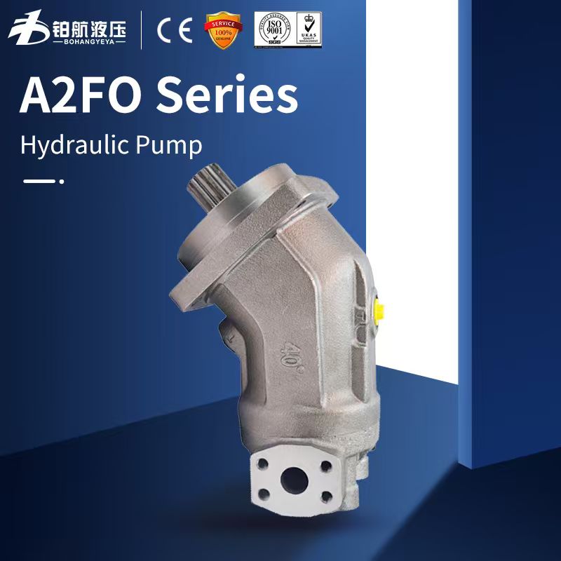
A2FO Series | Fixed Displacement Axial Piston Pump
Does a Hydraulic Pump Create Pressure or Flow?
A hydraulic pump primarily creates flow. Pressure develops when the flow meets resistance. Consider a pump sending oil through an open valve directly back to the reservoir. Oil is moving through the circuit, but pressure remains relatively low because the return path provides little resistance.
Now direct the same flow into a cylinder that must lift a heavy load. The cylinder cannot move until hydraulic force becomes sufficient to overcome the load and system losses. Pressure rises while the pump continues to deliver oil.
The pump must still be designed for the required working pressure. Its housing, shaft, bearings, seals and pumping components must tolerate the mechanical loads created during operation.
This relationship is important during troubleshooting. A low pressure reading does not automatically prove that the pump is damaged. Possible causes include:
- A relief valve that is set too low
- An open flow path to the reservoir
- Internal leakage in a cylinder or hydraulic motor
- Leakage through a control valve
- Insufficient pump drive speed
- Incorrect pump rotation
- A damaged drive coupling
- An inaccurate pressure test
The complete circuit should be checked before the pump is replaced. Hydraulic power unit troubleshooting guidance identifies incorrect rotation, low oil level, inlet restrictions, relief valve settings and priming problems as possible causes of weak or unstable hydraulic performance.
Technician's Tip: Measure both pressure and flow when diagnosing a hydraulic system. A pressure gauge alone cannot confirm whether the pump is delivering the required oil volume under load.
How Does a Hydraulic Pump Work?
The energy transfer process can be summarized as follows: Engine or motor → pump shaft → hydraulic fluid flow → system resistance → hydraulic pressure → actuator force or torque
As the pump shaft rotates, internal chambers expand near the inlet. This expansion lowers the local inlet pressure. Pressure acting on the fluid in the reservoir then helps move oil into the pump.
The pumping components trap the oil and carry it toward the outlet. The internal chambers become smaller near the discharge side, forcing oil into the hydraulic circuit.
People often describe this process by saying that the pump sucks oil from the reservoir. A more accurate explanation is that the pump creates a lower pressure area at the inlet. The surrounding pressure then moves the oil toward that area.
The inlet line must allow oil to reach the pump freely. An excessively long or narrow hose can restrict the oil supply. A blocked strainer, low oil level, air leak, cold oil or excessive shaft speed can also reduce inlet flow.
Poor inlet conditions may cause cavitation. Cavitation occurs when local pressure becomes low enough for vapor bubbles to form in the oil. These bubbles may collapse when they enter a higher pressure area inside the pump. Repeated bubble collapse can cause noise, vibration, surface damage and reduced pump performance.
Three Main Types of Hydraulic Pumps
Gear pumps, vane pumps and piston pumps are commonly used in industrial and mobile hydraulic systems.
| Pump Type | How It Moves Oil | Main Strengths | Points to Consider | Typical Applications |
| Gear pump | Meshing gears carry oil around the pump housing | Simple construction, compact size and practical cost | Flow pulsation and noise may be higher | Agricultural equipment, forklifts and basic power units |
| Vane pump | Sliding vanes form expanding and contracting chambers | Smooth flow and relatively quiet operation | Fluid cleanliness and viscosity require attention | Machine tools, presses and industrial power units |
| Piston pump | Pistons move inside a rotating or stationary cylinder block | High pressure capability and flexible control options | More complex construction and greater contamination sensitivity | Excavators, mining equipment, presses and hydrostatic drives |
Gear Pumps
A gear pump normally uses two rotating gears inside a close fitting housing. Oil enters the spaces between the gear teeth and the housing. The gears carry the oil around the outside of the pumping chamber. The oil is discharged when the teeth mesh again near the outlet.
Gear pumps are often selected for systems with steady flow demand and relatively simple control requirements. Their construction can make installation and maintenance straightforward.
Bohang's AZPF external gear pump range covers displacements from 4 to 28 cubic centimeters per revolution. The listed continuous pressure reaches 250 bar, while intermittent pressure reaches 280 bar for suitable models and operating conditions.
A gear pump may be suitable when:
- The required flow remains relatively stable.
- The hydraulic circuit is simple.
- Compact dimensions are important.
- Initial cost is an important consideration.
- Advanced displacement control is not required.
Vane Pumps
A vane pump contains a rotor with slots and sliding vanes. The rotor turns inside a cam ring. As it rotates, the spaces between the vanes become larger near the inlet and smaller near the outlet.
The changing chamber volume draws oil into the pump and displaces it through the outlet. This arrangement can provide smooth and relatively quiet delivery.
Vane pumps are commonly used in industrial equipment where stable movement and controlled noise are important. Typical applications include machine tools, presses, test stands and hydraulic power units.
The internal vanes and running surfaces depend on suitable lubrication. Incorrect oil viscosity or uncontrolled contamination can increase wear and reduce service life.
Bohang offers PVV fixed displacement vane pumps as part of its hydraulic pump product range. The final operating limits should be confirmed for the selected displacement, speed, fluid and duty cycle.
Piston Pumps
A piston pump uses several pistons arranged inside a cylinder block. In many axial piston designs, a swashplate controls piston movement.
As the cylinder block rotates, the pistons move in and out of their bores. The increasing chamber volume allows oil to enter. The decreasing chamber volume forces oil toward the outlet.
Changing the swashplate angle can change piston travel and pump displacement. This allows many piston pumps to adjust output according to pressure, load demand or an external control signal.
Piston pumps are commonly used when a system requires:
- High operating pressure
- Variable flow
- Pressure compensation
- Load sensing
- Precise actuator control
- High power density
- Open circuit or closed circuit operation
Bohang lists the A10VO open circuit variable pump range with displacements from 18 to 140 cubic centimeters per revolution. Its product range also includes A4VG heavy duty variable pumps for closed circuit applications. The exact size, controller, pressure rating and speed limit should be checked before selection.
The pump family name does not provide enough information to confirm suitability. The complete model code, circuit type, displacement, controller and mechanical interface must also match the equipment.
Fixed Displacement or Variable Displacement?
A fixed displacement pump moves approximately the same theoretical amount of oil during each shaft revolution. When the shaft speed remains constant, theoretical flow also remains constant.
This design is often suitable when:
- Flow demand remains stable.
- The hydraulic circuit is simple.
- Initial cost is important.
- Straightforward servicing is preferred.
- The system does not require advanced flow control.
A variable displacement pump can change the amount of oil delivered during each revolution. The adjustment may respond to pressure, load demand, mechanical input or an electronic control signal.
Variable output is useful when machine functions change during operation. An excavator may require different flow while lifting the boom, moving the arm, operating the bucket, swinging or travelling.
A pressure compensated pump can reduce displacement when system pressure reaches its control setting. The pump then delivers only the flow required to maintain the selected pressure and satisfy system demand.
A constant speed conveyor may operate effectively with a fixed displacement pump. A machine with frequently changing speeds and loads may benefit from variable displacement. The actual operating cycle should guide the decision.
Two Useful Hydraulic Pump Calculations
Basic calculations can help estimate pump size and drive power. Final selection should still be checked against the performance data for the exact pump model.
Estimate Pump Flow
Use the following equation: Actual flow in L/min = displacement in cm³/rev × speed in rpm × volumetric efficiency ÷ 1,000
Consider a pump with a displacement of 50 cubic centimeters per revolution. The pump operates at 1,500 revolutions per minute.
The theoretical flow is: 50 × 1,500 ÷ 1,000 = 75 L/min
If the estimated volumetric efficiency is 90 percent, actual flow is: 75 × 0.90 = 67.5 L/min
Volumetric efficiency compares actual pump output with theoretical flow. The value may decrease as internal leakage and component wear increase.
Estimate Hydraulic Power
Use the following equation: Hydraulic power in kW = pressure in bar × flow in L/min ÷ 600
At 200 bar and 60 liters per minute, hydraulic output is: 200 × 60 ÷ 600 = 20 kW
The electric motor or engine must provide more than 20 kilowatts because mechanical and volumetric losses occur inside the pump and drive system.
Final drive sizing should also consider:
- Startup conditions
- Peak pressure
- Maximum flow demand
- Pump efficiency
- Drive efficiency
- Operating temperature
- Machine duty cycle
- An appropriate service margin
How to Choose the Right Hydraulic Pump
A model number or outside dimension is not enough to select a replacement pump. Two pumps may look similar but use different shafts, ports, controls or pressure ratings.
Before requesting a quotation, collect the following information.
Hydraulic Requirements
- Required flow
- Normal working pressure
- Maximum pressure
- Pump displacement
- Drive speed
- Open circuit or closed circuit
- Fixed displacement or variable displacement
- Required control type
Mechanical Requirements
- Rotation direction
- Mounting flange
- Shaft type
- Shaft dimensions
- Port type
- Port size
- Port position
- Case drain connection
- Available installation space
Operating Conditions
- Hydraulic fluid type
- Expected oil temperature
- Ambient temperature
- Daily operating hours
- Continuous or intermittent operation
- Equipment application
- Required fluid cleanliness
- Noise requirements
Replacement Information
- Complete model code
- Clear nameplate photograph
- Photographs from several angles
- Shaft and flange dimensions
- Port measurements
- Machine make and model
- Description of the original problem
A pump with the correct displacement may still be unsuitable if its rotation, shaft, flange, ports, controls, pressure rating or drain arrangement does not match the machine.
Bohang supplies gear pumps, vane pumps and piston pumps for open and closed circuit systems. Its product range serves construction machinery, agricultural equipment, material handling equipment and industrial hydraulic systems.
Common Problems and What to Check
| Symptom | Possible Causes | First Checks |
| Whining or rattling | Cavitation, air entry, low oil level or restricted inlet | Check oil level, suction hose, strainer, viscosity and inlet connections |
| Slow actuator movement | Low pump flow, low drive speed, internal leakage or blocked filter | Measure pump speed and actual flow under load |
| Low system pressure | Relief valve fault, pump wear, valve leakage or actuator leakage | Measure pressure and flow across the complete circuit |
| Excessive oil temperature | Continuous bypass flow, low efficiency, unsuitable viscosity or poor cooling | Check relief settings, oil temperature, cooler condition and pressure losses |
| Shaft seal leakage | Excessive housing pressure, blocked case drain or shaft misalignment | Inspect the drain line, coupling and pump mounting |
| Foamy oil | Air entering the system, low tank level or return flow turbulence | Inspect suction connections and reservoir layout |
Conclusion
A hydraulic pump converts mechanical input into hydraulic fluid flow. Pressure develops when that flow meets resistance, allowing the hydraulic system to perform useful work.
Correct pump selection requires more than checking maximum pressure. Flow, displacement, speed, circuit type, control method, oil, mounting dimensions and operating cycle should all be confirmed.
When replacing an existing pump, begin with the machine’s operating requirements and the complete pump model code. Do not rely only on outside dimensions or a general pump type.
Bohang supplies gear, vane and piston pumps for mobile and industrial equipment. Its range includes fixed and variable displacement units for open and closed circuits.
FAQ
Q1. What Is the Main Purpose of a Hydraulic Pump?
A: A hydraulic pump converts mechanical shaft input into hydraulic fluid flow. The flow allows pressure to develop when it meets resistance, enabling cylinders and hydraulic motors to move a load.
Q2. What Is the Difference Between a Hydraulic Pump and a Hydraulic Motor?
A: A hydraulic pump receives mechanical power and produces hydraulic fluid flow. A hydraulic motor receives pressurized flow and produces rotary mechanical output.
Q3. Which Pump Type Is Suitable for High Pressure?
A: Piston pumps are commonly used in demanding high pressure applications. The correct pump must also match the required flow, circuit type, control method, shaft speed, fluid and operating cycle.
Q4. Can a Hydraulic Pump Be Repaired?
A: Many hydraulic pumps can be repaired when the housing and major internal parts remain within service limits.
The original cause of failure should also be identified. A repaired pump may fail again if contamination, cavitation, misalignment or an incorrect system setting remains uncorrected.