
Hydraulic systems power excavators, presses, agricultural machinery, lifting equipment and material-handling vehicles. Their value is not simply "high pressure." A well-designed system can transmit substantial power through compact components, provide smooth control and protect machinery against overload.
The technology also has major industrial importance. U.S. hydraulic product shipments reached an estimated $17.6 billion in 2024, representing 76% of total fluid-power shipments. Construction machinery, agricultural machinery, material handling, heavy trucks and automotive applications together represented 57% of hydraulic product sales.
For users, however, the practical questions are more immediate:
- What does each component do?
- Why is the machine slow or overheating?
- Which type of hydraulic circuit is installed?
- How should a replacement pump, motor or valve be selected?
What Is a Hydraulic System?
A hydraulic system transfers and controls energy with pressurized liquid, normally hydraulic oil. The fluid is not perfectly incompressible, but it resists compression enough to produce firm, controllable motion in most industrial machines.
Pascal's principle explains hydraulic force multiplication: pressure applied to a confined fluid is transmitted through that fluid. The basic relationship is: Force = Pressure × Effective Area
For example, at 200 bar, a cylinder with an effective piston area of 50 cm² produces a theoretical extension force of approximately: 200 bar × 50 cm² = 100 kN
That is about 10.2 metric tonnes-force. Actual output will be lower because pressure losses, seal friction and mechanical efficiency must be considered.
Three relationships are especially useful when operating or diagnosing a hydraulic system:
- Pressure primarily determines cylinder force or hydraulic motor torque.
- Flow primarily determines cylinder speed or hydraulic motor speed.
- Hydraulic power depends on both pressure and flow.
For metric units, theoretical hydraulic power can be estimated with: Power (kW) = Pressure (bar) × Flow (L/min) ÷ 600
A circuit operating at 200 bar and 60 L/min therefore transmits about 20 kW before efficiency losses. These relationships are more useful than looking at pressure alone when matching a hydraulic pump to a cylinder or hydraulic motor.
How Does a Hydraulic System Work?
Most hydraulic systems follow the same basic energy path: Engine or electric motor → hydraulic pump → hydraulic valves → cylinder or hydraulic motor → return line → reservoir
1. The Hydraulic Pump Creates Flow
An engine or electric motor rotates the hydraulic pump. The pump draws oil from the reservoir and delivers a specific volume of fluid into the pressure line.
A common misunderstanding is that the pump creates pressure by itself. More accurately, a hydraulic pump creates flow. Pressure rises when that flow meets resistance from a load, actuator, valve, hose or restriction.
The same pump may circulate oil at relatively low pressure while the machine is unloaded, then operate at much higher pressure when a cylinder begins lifting a load.
This distinction matters during troubleshooting. A pressure gauge may show high pressure even when the machine is moving slowly. The cause could be insufficient pump flow, a restricted valve, excessive load or internal leakage rather than a lack of pressure.
2. Hydraulic Valves Control the Flow
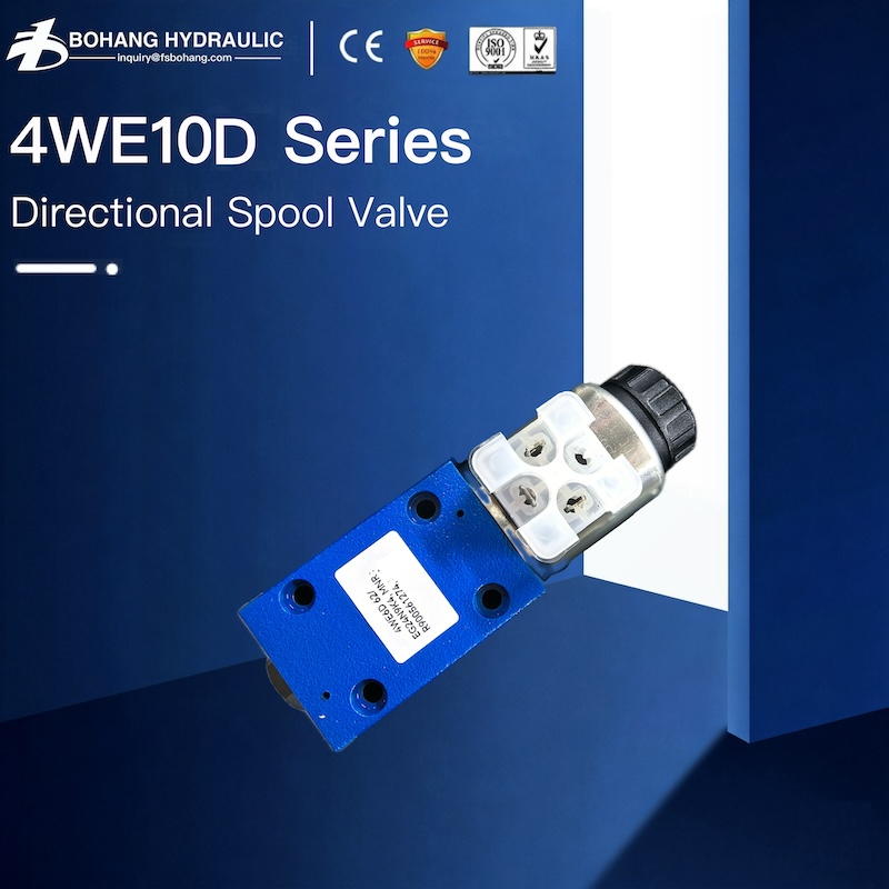
Oil from the pump reaches one or more hydraulic valves. Each valve has a specific control function:
- A directional control valve makes a cylinder extend or retract, or changes the rotation direction of a hydraulic motor.
- A pressure relief valve limits maximum circuit pressure.
- A flow-control valve regulates actuator speed.
- A check valve allows flow in one direction and prevents reverse flow.
- A counterbalance valve controls an overrunning or suspended load.
- A proportional valve varies pressure or flow according to an electrical command.
A valve must be selected for both pressure and flow. A valve may have an adequate pressure rating but still be too small for the pump output. Excessive flow through an undersized valve creates pressure loss, heat and slow actuator movement. Bohang's hydraulic valve range includes directional, pressure-control, flow-control, check and proportional valve configurations for different industrial and mobile circuits.
3. The Actuator Performs the Work
A hydraulic cylinder converts fluid power into linear force. A hydraulic motor converts it into rotary torque and speed.
Oil entering one side of an actuator displaces oil from the other side. The displaced oil returns through the control valve and filtration path before being reused.
4. The Oil Is Conditioned for Reuse
The reservoir stores hydraulic fluid and provides space for:
- Heat dissipation
- Air release
- Water and contaminant settling
- Volume changes during cylinder movement
Filters remove particles, while a cooler controls temperature when natural heat rejection is insufficient. Oil then returns to the pump and the operating cycle continues.
Main Hydraulic System Components
| Component | Main function | Important selection data |
|---|---|---|
| Reservoir | Stores and conditions hydraulic fluid | Volume, breather and return arrangement |
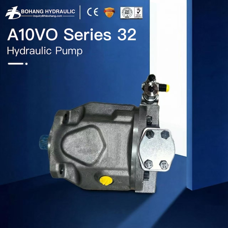
| Hydraulic pump | Converts mechanical input into oil flow | Displacement, speed, pressure and control |
| Hydraulic valves | Control direction, pressure and flow | Function, flow capacity and pressure rating |
| Cylinder | Produces linear movement and force | Bore, rod, stroke and mounting |
| Hydraulic motor | Produces rotary movement and torque | Displacement, speed and pressure difference |
| Filter | Controls particle contamination | Filtration efficiency and flow capacity |
| Hoses and tubes | Carry fluid between components | Size, pressure, temperature and fluid compatibility |
| Accumulator | Stores hydraulic energy | Volume, precharge and pressure ratio |
| Cooler | Removes heat | Heat load, oil flow and cooling medium |
Choosing the Right Hydraulic Pump
Common hydraulic pump designs include gear, vane and piston pumps.
Gear pumps are simple and economical. They are widely used in basic industrial systems, agricultural equipment and mobile power units.
Vane pumps generally provide smoother flow and lower noise. They are often used in machine tools and industrial hydraulic power units.
Axial piston and bent-axis pumps are suited to higher pressures, variable displacement and more demanding control requirements.
Bohang's product range includes fixed and variable displacement pumps for both open- and closed-circuit applications.
Do not select a pump from displacement or maximum pressure alone. Confirm:
- Required flow at the actual drive speed
- Continuous and peak pressure
- Open- or closed-circuit design
- Fixed or variable displacement
- Rotation direction
- Shaft and mounting flange
- Port type, size and position
- Control or regulator code
- Fluid viscosity and temperature
- Duty cycle
- Available engine or motor power
An oversized pump can be as problematic as an undersized pump. Unused flow may be forced across a valve or relief path, converting input power directly into heat.
Choosing the Right Hydraulic Motor
Hydraulic motors should be selected from the required shaft speed and torque rather than from displacement alone.
Gear and orbital motors suit many economical low-to-medium-speed duties. Axial piston and bent-axis motors are commonly used where higher power density, speed or pressure is required. Radial piston motors are often selected for very high torque at low speed.
For a replacement hydraulic motor, verify:
- Maximum and continuous speed
- Required torque
- Continuous and peak pressure difference
- Starting efficiency
- Case-drain arrangement
- Permissible return and case pressure
- Mounting flange
- Shaft type
- Port size and position
- Open- or closed-circuit approval
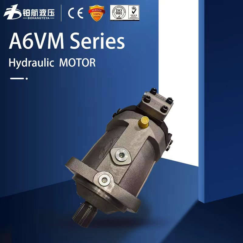
Two motors with the same displacement are not automatically interchangeable. Differences in shafts, case drains, controls, pressure ratings and installation dimensions can prevent reliable operation. Bohang supplies fixed and variable displacement piston motors in multiple mounting and circuit configurations.
Open and Closed Hydraulic Circuits
A hydraulic circuit is the organized flow path connecting the components required to perform a specific machine function.
Open Hydraulic Circuit
In an open circuit, the pump draws oil from the reservoir. Oil passes through a valve and actuator before returning to the reservoir.
Open circuits are practical when one pump supplies:
- Multiple hydraulic cylinders
- Several valve sections
- Auxiliary hydraulic motors
- Different machine functions
Returning oil can be filtered, cooled and deaerated before entering the pump again. This makes open circuits common in presses, lifting equipment, construction machinery and industrial power units.
Closed Hydraulic Circuit
In a closed circuit, the main oil flow travels from the pump to a hydraulic motor and directly back to the pump.
Reversing the pump flow can reverse the motor without sending the full working flow through a conventional directional valve. This makes closed circuits useful for compact, reversible hydrostatic drives such as travel drives, conveyors and rotating drums.
However, a closed circuit is not simply an open circuit without a large reservoir. It normally requires:
- A charge pump
- Low-side pressure control
- High-pressure protection on both loop sides
- Flushing flow
- Filtration
- Cooling
- Correct braking control
The circuit should therefore be selected from the machine's real duty cycle, not from the assumption that one architecture is always more efficient.
Important: Open circuit is not the same as open-center valving. Open circuit describes the main oil path. Open center describes a directional valve condition that provides an open flow path, commonly to the reservoir, when the valve is in neutral.
How to Read a Basic Hydraulic Circuit
When reading a schematic, do not try to understand every line at once. Use this sequence:
- Find the reservoir and hydraulic pump.
- Identify the main pressure and return lines.
- Locate the pressure relief valve.
- Identify the directional valve and its spool positions.
- Trace flow from the pump to the actuator.
- Trace displaced oil back to the reservoir or pump.
- Check pilot, drain, load-sense and case-drain lines separately.
- Review what happens in neutral, working and overload conditions.
This process helps determine whether a problem begins at the power source, the control section or the actuator.
Hydraulic System Troubleshooting: Measure Before Replacing Parts
A slow machine does not automatically need a new hydraulic pump. The same symptom can result from low pump flow, a restricted valve, excessive load, high oil viscosity, internal leakage or a blocked pump inlet.
Start with four measurements:
- Pressure: Does the system reach its specified pressure under load?
- Flow: Does pump output remain adequate as pressure and temperature increase?
- Temperature: Is excessive heat reducing viscosity and increasing leakage?
- Case-drain flow: Has internal leakage increased inside the pump or motor?
| Symptom | Checks to prioritize |
| Entire machine is slow | Pump speed, inlet condition, pump flow and main relief setting |
| One function is slow | Valve section, flow control, hose restriction and actuator leakage |
| Oil overheats | Relief bypass, throttling, internal leakage and cooler performance |
| Pump is noisy | Oil level, inlet restriction, aeration, cavitation and alignment |
| Cylinder drifts | Directional valve, load-holding valve and piston seals |
| Motor lacks torque | Pressure difference, relief setting, motor leakage and load |
Fluid cleanliness deserves particular attention. A hydraulic filtration handbook reports that, in the experience of its designers and users, more than 85% of hydraulic and lubrication-system failures are directly associated with contamination. The percentage should not be treated as a universal prediction for every machine, but it demonstrates why filtration, clean assembly and controlled oil handling must be planned before failures begin.
Replacement Pump, Motor or Valve Checklist
Before requesting a quotation, collect the information that determines whether the component will fit and operate correctly:
- Complete manufacturer and model code
- Clear nameplate and component photographs
- Machine type and required function
- Displacement, flow and speed
- Working and peak pressure
- Rotation direction
- Open or closed circuit
- Mounting flange and pilot diameter
- Shaft type and dimensions
- Port thread, size and position
- Pump control or valve actuation type
- Case-drain requirement
- Hydraulic fluid and operating temperature
- Quantity and required delivery date
Matching displacement alone can result in the wrong shaft, ports, control, pressure rating or case-pressure limit.
When an original component is obsolete, difficult to source or unsuitable for a changed operating condition, a customized hydraulic pump, hydraulic motor or hydraulic valve may be safer than adapting an incorrect standard part. Bohang provides component selection and custom hydraulic solutions for applications requiring specific pressure, flow, mounting and control configurations.
Hydraulic Safety and Maintenance Essentials
Hydraulic systems can retain energy after the engine or motor stops. Lower suspended loads, isolate the power source and release stored pressure according to the machine’s approved lockout procedure before service.
Never search for a high-pressure leak with your hand. Escaping oil can penetrate skin, while high-pressure oil mist can create a serious fire hazard.
OSHA reports that typical petroleum-based hydraulic fluids may have flash points of approximately 300–600°F and auto-ignition temperatures of 500–750°F. When pressurized oil forms a fine mist near an ignition source, it can ignite violently. Hoses, tubes and fittings should therefore be inspected for leakage, blistering, deformation and damaged connections.
Routine maintenance should include:
- Checking oil level, temperature and visible leakage
- Inspecting hoses for abrasion, cracking and deformation
- Monitoring filter indicators and breathers
- Sampling oil at defined intervals
- Checking pump inlet and case-drain conditions
- Cleaning coolers and cooling fans
- Verifying relief and control settings after repairs
Build the Hydraulic System Around the Required Work
The best hydraulic system is not the one with the largest pump or highest pressure rating. It is the system whose pump flow, actuator size, valve capacity, circuit architecture, filtration and cooling match the real load and duty cycle.
When selecting or replacing a hydraulic pump, hydraulic motor or hydraulic valve, begin with the required force, torque, speed and operating pattern. Then verify every hydraulic and mechanical interface. This reduces overheating, unstable movement, premature wear and installation errors.
For component identification or a customized hydraulic solution, provide the complete model code, nameplate photographs, operating pressure, required flow, mounting dimensions and application details.
A complete technical request allows compatibility to be evaluated before quotation and helps the replacement component work as part of the entire hydraulic circuit—not merely fit into the available space.
FAQ
Q1. What are the most important parts of a hydraulic system?
A: The pump supplies oil flow, valves control that flow, and cylinders or hydraulic motors convert it into mechanical work. The reservoir, filters, cooler, conductors and safety devices keep the circuit reliable and controllable.
Q2. Does Higher Pressure Make a Hydraulic Motor Run Faster?
A: No. Flow and motor displacement primarily determine speed. Pressure difference primarily determines available torque. A motor may run slowly while system pressure is high if flow is restricted or internal leakage has increased.
Q3. How Do I Choose Between an Open and Closed Circuit?
A: Use an open circuit when a reservoir and valve bank must serve cylinders or several actuators. Consider a closed circuit for compact, reversible hydraulic motor drives. Cooling, braking, control and maintenance requirements must also be included in the decision.
Q4. Why Does Hydraulic Oil Overheat?
A: Common causes include continuous relief-valve bypass, undersized valves, excessive throttling, internal leakage, high return pressure and inadequate cooling. Measure pressure, flow and temperature before replacing components.