

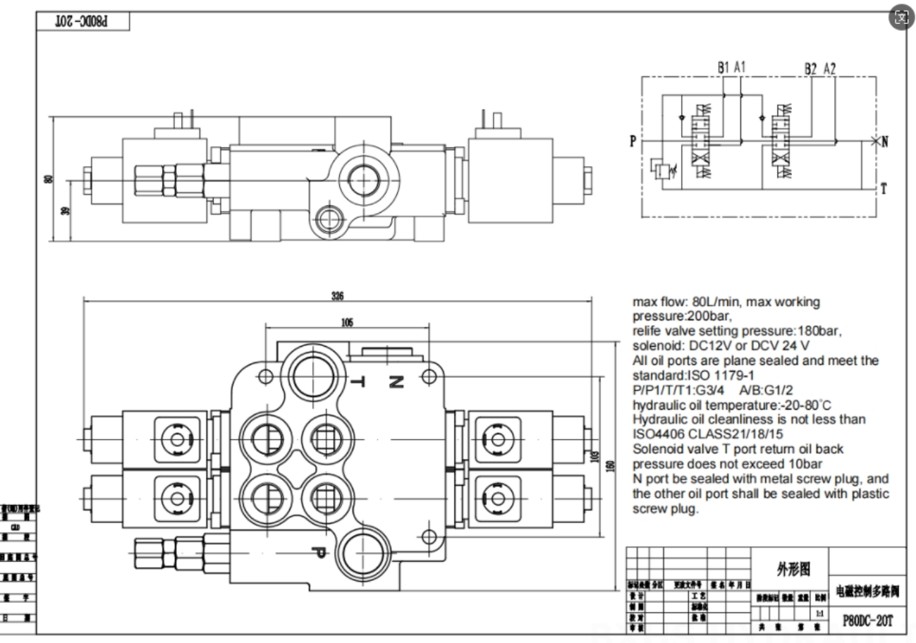
A hydraulic system should be designed together with its machine. Selecting a pump first and building everything else around it often causes excessive energy use, slow movement, overheating or poor control.
Good design starts with load and motion requirements. Engineers then determine actuator size, pressure, flow, control methods and supporting components. Final goals are simple: reliable movement, safe operation, reasonable energy use and easy maintenance.
Hydraulic System Design Process at a Glance
A practical design process can be divided into six stages:
- Define machine functions and operating conditions.
- Select hydraulic cylinders or motors.
- Calculate required pressure and flow.
- Develop speed, pressure and sequence-control circuits.
- Select pumps, valves and auxiliary components.
- Draw the schematic and verify system performance.
These stages may overlap. Changing cylinder size, actuator speed or working cycle can affect pump capacity, valve size, motor power and cooling requirements.
1. Define System Requirements
Start with required force or torque, movement speed, cylinder stroke, motor rpm and cycle time. Identify normal load, maximum load, shock load and any suspended or overrunning load. Also determine how many actuators must move at once and which movements follow a fixed sequence.
Working environment also affects system design. Temperature, dust, humidity, vibration, corrosion, noise limits and available installation space may influence fluid, seals, filters, coolers and component materials.
Safety requirements should cover overload, power loss, hose failure and emergency stop. A suspended load, for example, normally needs a counterbalance valve or pilot-operated check valve rather than relying only on a directional valve.
Efficiency, maintenance access and project cost should be considered at this stage instead of after component selection.
2. Select Hydraulic Actuators
Choose a hydraulic cylinder for linear movement and a hydraulic motor for rotary movement.
Cylinder selection depends on required force, working pressure, stroke, speed, mounting and available space. Extension and retraction must be checked separately because rod area changes available force and movement speed.
Motor selection depends on required torque, speed, displacement and pressure. Starting torque, minimum stable speed, rotation direction, shaft load, case drain and braking requirements also matter.
Two basic relationships guide actuator sizing:
Pressure mainly determines force or torque.
Flow mainly determines cylinder speed or motor speed.
Actuator sizing should include mechanical efficiency and pressure loss. Long-stroke cylinders also need a rod-buckling check, while motors need protection against overspeed or uncontrolled loads.
3. Develop a Speed-Control Plan
Motion direction is normally controlled by directional valves or logic elements. Small and medium-flow systems often use spool valves. High-flow systems may use cartridge valves with pilot control.
Three common speed-control approaches are available:
| Control method | Main advantage | Main limitation | Suitable applications |
|---|---|---|---|
| Throttle control | Simple and economical | Pressure loss becomes heat | Small-power or intermittent systems |
| Volumetric control | Higher efficiency | More complex pump or motor control | High-power and long-duty systems |
| Combined control | Good efficiency and stable speed | Requires coordinated pump and valve settings | Precision or variable-load equipment |
Throttle Control
Throttle control usually combines a fixed-displacement pump with a flow-control valve. Changing valve opening changes flow entering or leaving an actuator.
Meter-in control regulates inlet flow and can reduce startup shock. Meter-out control regulates return flow and is useful when a load may drive an actuator faster than supplied flow. Bypass control diverts part of pump delivery back to a reservoir.
This method is easy to apply, but unused flow may pass across a relief valve. Energy lost through relief and throttling appears as heat.
Volumetric Control
Volumetric control changes pump or motor displacement. A variable pump can reduce output when demand falls, limiting unnecessary throttling and relief losses.
This approach suits machines with changing loads, long working cycles or high power. Added efficiency comes with higher component cost and more complex adjustment.
Combined Control
A combined system uses a variable pump with a flow-control or proportional valve. Pump delivery follows general demand, while valve control provides stable speed and smoother movement.
Such systems offer good performance but require correct pressure margins between pump control and valve control.
4. Develop Pressure and Sequence Control
A hydraulic system must maintain enough pressure for normal work while protecting every component from overload.
Fixed-pump systems commonly use relief valves to limit maximum pressure. Variable-pump systems may use pressure compensation during normal operation while a safety valve provides final protection.
When one branch needs lower pressure than main supply, a pressure-reducing valve can provide suitable control. If a pump continues running during idle periods, an unloading circuit can reduce power loss and heat.
Some applications need a small amount of oil at a pressure higher than normal system pressure. An intensifier circuit may provide this function without adding a separate high-pressure pump.
Bohang's hydraulic valve range covers direction, pressure and flow-control functions for industrial and mobile systems.
Sequence Control
Machine movements may be controlled by position, pressure, time or electronic commands.
Position switches and sensors are suitable when a following action must start at a specific location. Pressure switches or sequence valves work well when another action should begin only after clamping or pressing reaches a specified load.
Time control can provide a simple delay, but load and oil temperature may change actual movement time. Complex machines often use sensors, solenoid valves and PLC control for better repeatability, interlocking and fault monitoring.
5. Select Hydraulic Power Source and Circuit Type
A hydraulic pump forms the core of a hydraulic power source. Pump flow should match actual system demand as closely as practical.
Fixed-displacement pumps suit simple systems with stable flow requirements. Variable-displacement pumps are better suited to changing loads, multiple functions and applications where energy efficiency is important.
Pump selection should consider flow, continuous pressure, peak pressure, speed, rotation, control type, shaft, flange, ports, fluid and duty cycle. Pressure and displacement alone are not enough to confirm compatibility.
When flow varies greatly during a cycle, designers may use multiple pumps, a variable pump or an accumulator. An accumulator can provide short-duration peak flow, maintain pressure or support limited emergency movement.
Open Circuit vs. Closed Circuit
| Item | Open circuit | Closed circuit |
|---|---|---|
| Main oil path | Reservoir to pump, actuator and back to reservoir | Pump to motor and directly back to pump |
| Common actuators | Cylinders and multiple functions | Reversible hydraulic motors |
| Main advantages | Simple filtration, cooling and air separation | Compact layout and efficient drive reversal |
| Additional needs | Reservoir, return filtration and cooling | Charge pump, flushing, cooling and loop protection |
Open circuits are common in industrial power units, lifting systems and machines with several cylinders. Closed circuits are common in travel drives, conveyors, winches and rotating drums.
Open circuit and open-center valve are different terms. Circuit type describes oil flow through a complete system. Valve-center type describes port connections when a directional valve is in neutral.
6. Select Supporting Components
Reliable performance depends on more than pumps and valves.
Reservoir and Filtration
A reservoir stores oil, accommodates cylinder-volume changes, helps release air and supports heat dissipation. Tank size should be checked against working cycle, oil-volume variation and cooling demand rather than chosen from one general rule.
Filtration should match cleanliness requirements of sensitive components. Filter location, flow capacity, dirt-holding capacity and clogging indication all require consideration.
Cooling and Fluid
Heat comes from pump inefficiency, throttling, continuous relief flow, pressure loss and internal leakage.
If natural heat dissipation cannot maintain suitable oil temperature, add a correctly sized cooler. Hydraulic fluid must also maintain acceptable viscosity during cold startup and normal operation.
Hoses and Pipes
Line size should be based on maximum flow, acceptable velocity and pressure loss. Check working pressure, peak pressure, temperature, bend radius and vibration.
Keep pump suction lines short, adequately sized and airtight. Excessive inlet restriction can cause noise, cavitation and pump damage.
Case-drain lines must follow component instructions and remain within permitted back-pressure limits.
7. Draw Hydraulic System Schematic
A complete schematic combines power supply, pressure control, speed control, direction control and actuator circuits.
Remove duplicated components when combining individual circuits. Check interactions between functions and review valve behavior in every operating position.
A clear schematic should identify pumps, cylinders, motors, valves, filters, coolers and accumulators. Pressure, return, pilot and drain lines should be easy to distinguish. Component numbers, solenoid codes, sensor references and actuator directions should also be shown.
Add pressure, temperature and flow test points at important locations. Proper test access makes commissioning and troubleshooting easier.
8. Verify System Performance
Before finalizing a hydraulic system, confirm five areas:
- Pressure and flow meet actuator requirements.
- Pump and prime mover can support a complete working cycle.
- Pressure loss and oil temperature remain acceptable.
- Suspended loads and stored pressure are controlled safely.
- Components can be inspected, adjusted and replaced without unnecessary disassembly.
Review startup, neutral, normal operation, overload, shutdown, power loss and emergency-stop conditions. A circuit that works correctly during normal movement may still be unsafe during a failure.
Common mistakes include selecting a pump too early, ignoring return flow, using undersized valves, operating continuously near relief pressure and failing to consider oil cleanliness or cooling.
Conclusion
Hydraulic system design begins with machine requirements and develops through actuator selection, circuit planning, component matching and performance verification.
A successful design provides required force and speed without unnecessary pressure, flow or complexity. It also controls heat, contamination and failure risks while supporting practical maintenance.
For a technical review, prepare machine type, load, speed, working pressure, required flow, duty cycle, existing model codes and installation dimensions.
Bohang provides custom hydraulic solutions based on pressure, flow, torque, mounting and control requirements. Contact Bohang Hydraulic for component matching, technical support or a quotation.