
Hydraulic symbols turn a complex fluid power system into a drawing that can be read and checked. They show component functions, port connections and expected flow paths. They do not show physical appearance or every specification needed for replacement.
Reading a symbol can help trace a fault or identify a component family. Selecting an actual pump, motor or valve still requires a model code, pressure and flow data, mounting details and control information.
What Are Hydraulic Symbols?
Hydraulic symbols are standardized graphical representations of pumps, motors, cylinders, valves, reservoirs, filters and other fluid power components. Lines between symbols represent flow paths, pilot connections, drains or mechanical relationships.
A symbol describes function rather than internal construction. Two pumps with different housings may share a symbol if they perform the same function. A pump symbol may not reveal whether a unit uses gears, vanes or pistons. Read a schematic with its legend, machine manual and data sheets.
Basic Symbol Grammar
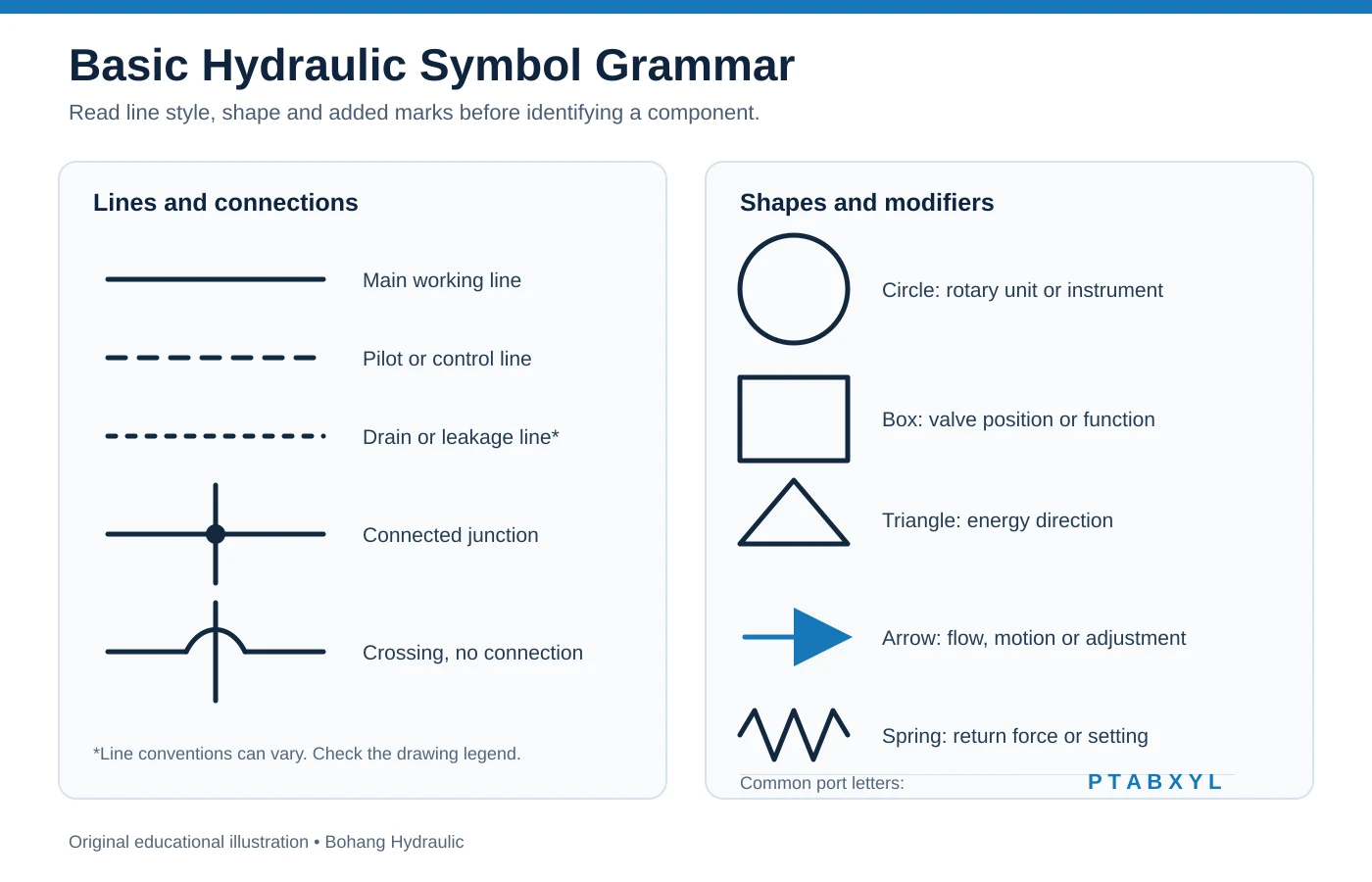
Most hydraulic symbols are built from a small set of shapes. Learning this visual grammar is more useful than trying to memorize an entire chart.
| Element | Common meaning |
|---|---|
| Circle | Pump, motor, measuring device or rotary component, depending on details inside it |
| Square or rectangle | Valve function, valve position or cylinder body |
| Triangle | Fluid energy direction in a pump or motor symbol |
| Arrow | Flow path, movement direction or adjustability |
| Spring | Return force or pressure setting |
| Solid line | Main pressure or return path |
| Dashed line | Pilot, control or signal connection |
| Dot at an intersection | Connected flow paths |
| Crossing without a dot | Lines cross but normally do not connect |
Port letters also carry useful information. P commonly identifies pressure supply, while T connects to tank. A and B are working ports. X and Y often identify external pilot supply and pilot drain. L may indicate leakage or case drain. Conventions vary, so confirm definitions in manufacturer documentation.
Common Hydraulic Symbols by Component
Hydraulic Pump and Motor Symbols
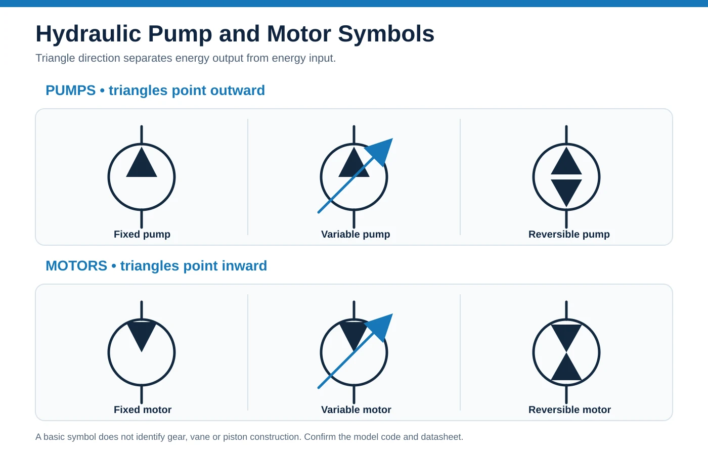
Pumps and motors are usually represented by circles containing one or more triangles. Triangle direction provides a quick distinction.
| Feature | Hydraulic pump | Hydraulic motor |
|---|---|---|
| Energy conversion | Mechanical input becomes hydraulic flow | Hydraulic flow becomes mechanical rotation |
| Triangle direction | Points outward from circle | Points inward toward circle |
| Diagonal arrow | Variable displacement or adjustable function | Variable displacement or adjustable function |
| Two opposing triangles | Reversible flow | Reversible rotation or bidirectional operation |
A symbol may indicate fixed or variable displacement, but it rarely confirms displacement, pressure rating, shaft, flange or control type. It should not be used alone to approve a replacement.
Hydraulic Cylinder Symbols
A cylinder symbol contains a body, piston line and rod. A single acting cylinder normally has one hydraulic port and returns through load, gravity or a spring. A double acting cylinder has two working ports for powered extension and retraction. Additional marks can identify cushioning, a double rod or spring return.
Follow both working lines during troubleshooting. Reversed A and B connections may reverse motion, while restricted return flow can slow movement or raise back pressure.
Directional Control Valve Symbols
Directional valve symbols look complex because they show several operating states at once. Each adjacent square represents one spool position. A 4/3 valve therefore has four ports and three positions. A 4/2 valve has four ports and two positions.
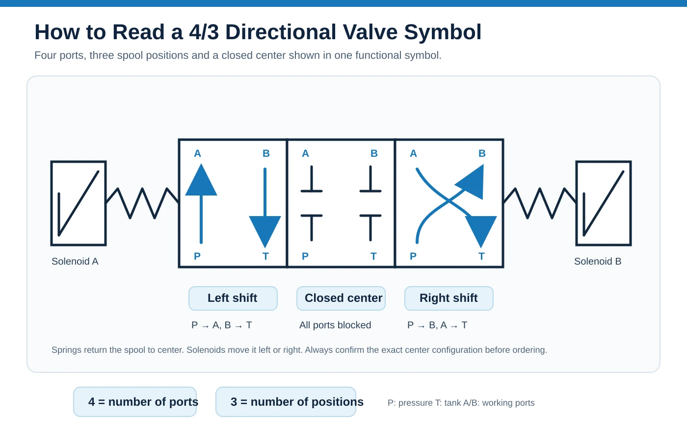
Arrows show connected ports and flow direction. A blocked end shows a closed port. Springs indicate a return or centered condition, while solenoid, lever, pilot or roller symbols identify actuation. Center configuration determines whether pump flow is unloaded, blocked or directed elsewhere when no command is active.
Pressure, Flow and Check Valve Symbols
Pressure relief valves limit circuit pressure by opening a path to tank at a set value. Pressure reducing valves maintain lower branch pressure. Sequence valves initiate another operation after pressure reaches a chosen level.
Flow control symbols use a restriction. A diagonal arrow usually marks adjustment. A throttle check valve combines restricted flow in one direction with free reverse flow. A check valve permits one-way flow, while a pilot line may indicate pilot-operated release.
Reservoirs and Auxiliary Components
Reservoir symbols can be open or pressurized. Filters commonly use a diamond with a dashed element. Accumulators show stored gas or spring energy. Coolers, gauges and test points often provide useful diagnostic clues.
How to Read a Hydraulic Schematic
Do not start with a complicated valve in the middle of a page. Use a consistent sequence.
- Find reservoir and pump. Confirm where oil enters the pump and which line carries supply flow.
- Follow main pressure line. Locate relief valve and note how excess pressure returns to tank.
- Identify directional valves. Count ports and positions, then find normal or centered state from springs and operators.
- Trace supply to each actuator. Follow P to A or B and note which cylinder chamber or motor port receives flow.
- Trace return path. Oil leaving an actuator must reach tank through a valid route.
- Check pilot and drain lines. Restrictions here can cause faults not explained by main flow paths.
- Compare every operating state. Read neutral, commanded movement and overload conditions separately.
Before service, isolate energy, release stored pressure and follow machine-specific lockout procedures. A schematic supports diagnosis but does not replace safety instructions.
Worked Circuit Example
Consider a circuit containing a reservoir, fixed displacement pump, pressure relief valve, spring-centered 4/3 directional valve and double acting cylinder.
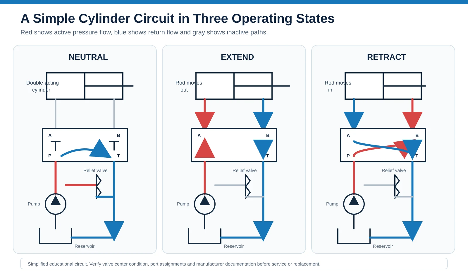
In neutral, center configuration determines system behavior. An open center can route pump flow to tank. A closed center blocks ports, causing pressure to rise until pressure control responds or a variable pump destrokes.
During extension, valve position may connect P to cap-end port A and B to T. During retraction, connections reverse. Two valves may fit the same mounting pattern yet produce different machine behavior, so complete spool symbols matter.
What Hydraulic Symbols Cannot Tell You
A schematic can identify function and circuit position, but it rarely confirms an exact replacement. Pump and motor selection also depends on displacement, rotation, pressure, speed, shaft, spline, flange, ports, drain limits, seals and control code. Valve selection requires spool configuration, mounting pattern, pressure, flow, voltage and connector.
Physical port location is another common source of error. A symbol shows functional connections, not necessarily where each port appears on a housing. A port marked A on a drawing may face a different direction on another valve version. Check dimensional drawings, port markings and installation clearance before disconnecting lines or approving a substitute.
Before requesting a quotation, collect:
- A clear schematic section with component reference number
- Full model code and a straight-on nameplate photo
- Photos showing shaft, flange, ports and controls
- Machine make, model and application
- Available pressure, flow, speed and displacement data
- Required rotation and circuit type
Use Bohang's pump and motor replacement checklist to compare these details before approving a substitute.
Common Mistakes and Practical Tips
Do not assume crossed lines connect. Look for a junction dot. Analyze one directional-valve position at a time. A diagonal arrow often marks adjustability, not flow. Do not identify gear, vane or piston construction unless supporting documents confirm it.
On an unfamiliar drawing, mark pressure, return, pilot and drain lines in different colors. Describe neutral and commanded states in plain words. This can expose a missing return path, unexpected center condition or overlooked pilot signal.
Frequently Asked Questions
Q1. What do hydraulic symbols represent?
A: They represent component functions, ports, control methods and flow relationships in a hydraulic circuit. They are not scaled pictures of actual parts.
Q2. How can I distinguish a pump from a motor symbol?
A: Look at triangle direction. A pump triangle points outward because mechanical energy becomes hydraulic flow. A motor triangle points inward because hydraulic energy produces mechanical rotation.
Q3. What does 4/3 mean on a directional valve?
A: It means four ports and three spool positions. Each square in its symbol shows port connections in one position.
Q4. Do hydraulic symbols show pressure and flow ratings?
A: Normally, no. Ratings must be confirmed from a model code, data sheet or manufacturer documentation.
Q5. Can a schematic identify an exact replacement?
A: It can narrow down component type and function, but exact selection still requires mechanical, hydraulic and control details.
From Hydraulic Symbols to a Suitable Component
Bohang supplies hydraulic pumps, hydraulic motors, hydraulic valves, piston pump and motor parts, and custom solutions for mobile and industrial equipment. Product coverage includes fixed and variable displacement units plus valves for direction, pressure and flow control.
Bohang can review more than a basic symbol. Model codes, operating data, mounting interfaces, shafts, ports and control requirements can be compared before a replacement is proposed. This helps buyers evaluate mechanical, hydraulic and control compatibility.
If you need help identifying a pump, motor or valve, send a clear schematic section, full model code, nameplate photos and available operating data. Bohang can use that information to review product options and prepare a more accurate quotation.